wheeeMorph - to morph 2 images - GIF/PNG/JPEG/other - using a barymetric technique on triangles
uniquename - 2014apr19
I recently (2014mar) posted 2 image processing scripts on this wiki:
tkMerge2Images - GIF/PNG/JPEG - with image-weighting & image-alignment options
tkImageGridWarp - GIF/PNG/JPEG/other - using a barymetric technique on triangles
I have had an image morphing utility on my Tcl-Tk 'to-do' list for about a year. Since morphing is basically a combination of warping along with merging/blending 2 images, I knew that I could 'borrow' a lot of code from the 2 scripts above to make a morphing utility.
It turns out that it was more challenging than I thought. There were a lot more changes and additions than I had counted on. It took almost a man-month of work to make the utility. But, as you will see in the images down this page, I managed to get some pretty good results.
---
One of the big differences between my 'tkImageGridWarp' script and this 'wheeeMorph' script is that there are 2 grids (on 2 canvases) required, rather than 1 grid (on one canvas).
Also, as I got into the development, I found that when I had the pointer positioned over a grid-point in one grid, I needed to provide a way to indicate the corresponding grid-point on the other grid.
And I kept finding new features (and procs) that I had to add as I did preliminary testing.
---
Like the 'tkImageGridWarp' script, this 'wheeeMorph' script does the warping by doing a mapping onto a warped grid --- BUT it is an 'intermediate' grid, between the 2 user-deformed grids --- not a single warped grid.
In the color-blending, like in the warping, I encountered a major difference: Instead of getting the color for a pixel on the 'intermediate' grid from ONE image, I had to find the color of the TWO corresponding pixels on the TWO user-deformed grids (grid1 and grid2), and blend those two colors.
The color-blending was more like the 'tkMerge2Images' script, in that 2 colors needed to be blended. But instead of the 2 colors coming from 2 UNWARPED grids/images, the 2 colors had to come from 2 WARPED grids.
---
Like the 'tkImageGridWarp' script, this 'wheeeMorph' script works its way over QUADRANGLES --- but on an 'intermediate' grid (grid3), a linear interpolation between 2 user-warped grids (3 warped grids involved) --- not quadrangles on a single user-warped grid.
For a given point on the 'intermediate' grid, this utility finds the two corresponding pixels on grids 1 and 2 by using triangles (two triangles in each quadrangle) --- by using 'barymetric coordinates' on each triangle.
The barymetric coordinates of a point in a triangle of the 'intermediate' grid (grid3) are calculated and then used to get the location of the corresponding point in the two corresponding triangles in the two user-deformed grids (grid1 and grid2).
---
Back on 2013sep05, I posted code using a barymetric technique --- at the wiki page
3-Color-Gradient Isosceles Triangle - Barymetric Blend with Shaded Edges
On that color-shaded-isoceles-triangle page, I present a Tk script that peforms a color blend using barymetric coordinates.
I used the same mathematics (and code) from that script to do the 'grid-warp' of the 'tkImageGridWarp' script --- and I used the same mathematics in this 'wheeeMorph' script.
See that wiki page above (#38676) for details on the barymetric mathematics involved and for further sources on barymetric coordinates and math.
---
THE GOALS
My main goals for the 'wheeeMorph' Tcl-Tk script were:
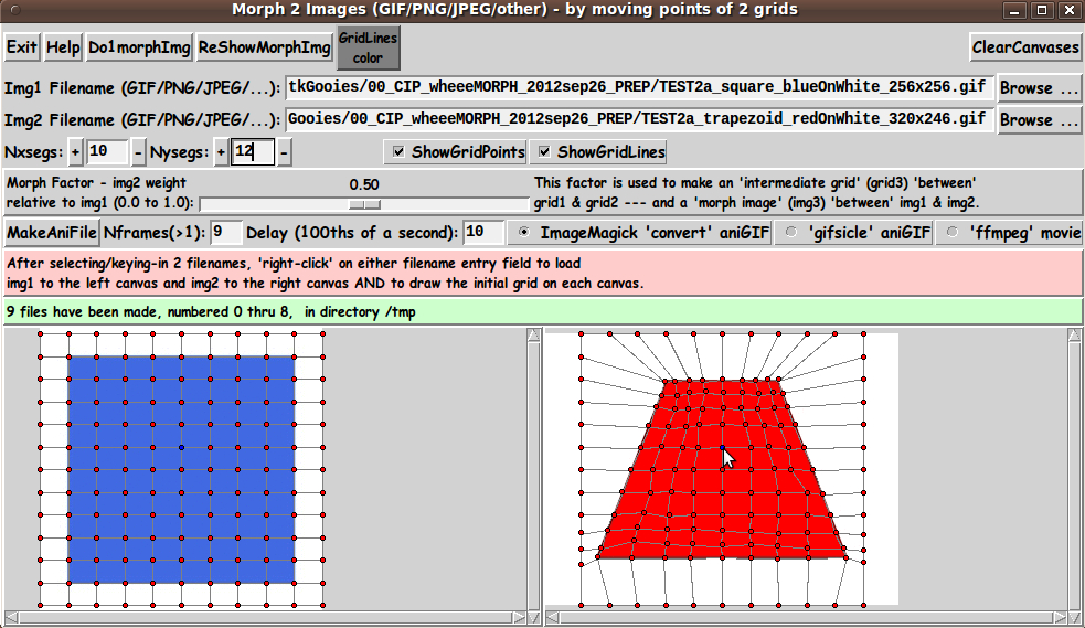
1) Provide a GUI for selecting a 2 image files (GIF, PNG, JPEG, or about 100 other types). (To make it easy on the user, my goal was to allow the 2 images to be of somewhat different sizes. This utility is to center the 2 images in the canvases and determine a 'common overlay area' on the 2 images --- and morph between the 'common overlay area' of the 2 images.)
2) Provide 2 side-by-side canvases on which to put the 2 images.
3) Provide a grid of movable points on each image in each canvas --- for the user to define the warp aspect of the 'morph'. (Allow the grid points on the outer edges to 'slide' along the edges, but not move 'inward' or 'outward'.)
4) Provide the user a way to easily change the 2 grids to have a different number of 'segments' in the x and y directions.
5) Provide a 'scale' widget on the GUI by which the user can specify a 'morph factor' with which to make a single morph image --- via a 'Do1MorphImg' button on the GUI.
6) The single morph image is mainly a way to check on the morph that may be created using the current deformation of the 2 grids. Actually, the desired end result of a 'morph' is usually to create an animation of the morph. It would be too tedious to built the animation via 'manual' creation of a sequence of images. So I wanted a 'MakeAniFile' button on the GUI, by which the user can easily create the animation with a mouse click.
7) To support making the animation, I needed to provide entry widgets by which the user can specify (1) the number of frames to be generated and (2) the 'delay-time' --- the amount of time each image-frame is to be shown.
8) I wanted to provide the user the option of creating either an animated-GIF file or a movie file. For animated-GIF's, I wanted to allow the user to use either the ImageMagick 'convert' command or the 'gifsicle' command. And for movies, I wanted to allow the user to use the 'ffmpeg' command --- by which an 'mp4' movie file would be created.
9) Provide a color selector option by which the color of the grid lines can be changed. (I originally was using yellow grid lines, but one of my first pair of test images was a yellow smiley face --- happy and sad. I could not see the grid lines on the two yellow smiley faces. I realized I would need to allow the user to choose the color of the grid lines.)
10) Provide a way to easily hide the grid (points and lines), so that a single warped image can be captured without the grid showing.
11) Devise the procs in the script in a modular fashion, so that essentially any operation can be done by the user, in almost any order, and reasonable results/responses will be obtained.
(I am currently not concerned with handling transparency in GIF and PNG images. So, in the code below, I have not included code to handle transparency information in either of those 2 types of image file.)
SCREENSHOT OF THE GUI
On the basis of the goals above (and after many days of coding and testing --- and re-coding and re-testing --- and re-coding and re-testing --- and wondering how many cycles of that iterative process I would have to endure), I ended up with the GUI seen in the following image.
Here is what the GUI looks like when it first comes up --- before the user has selected 2 files to process.
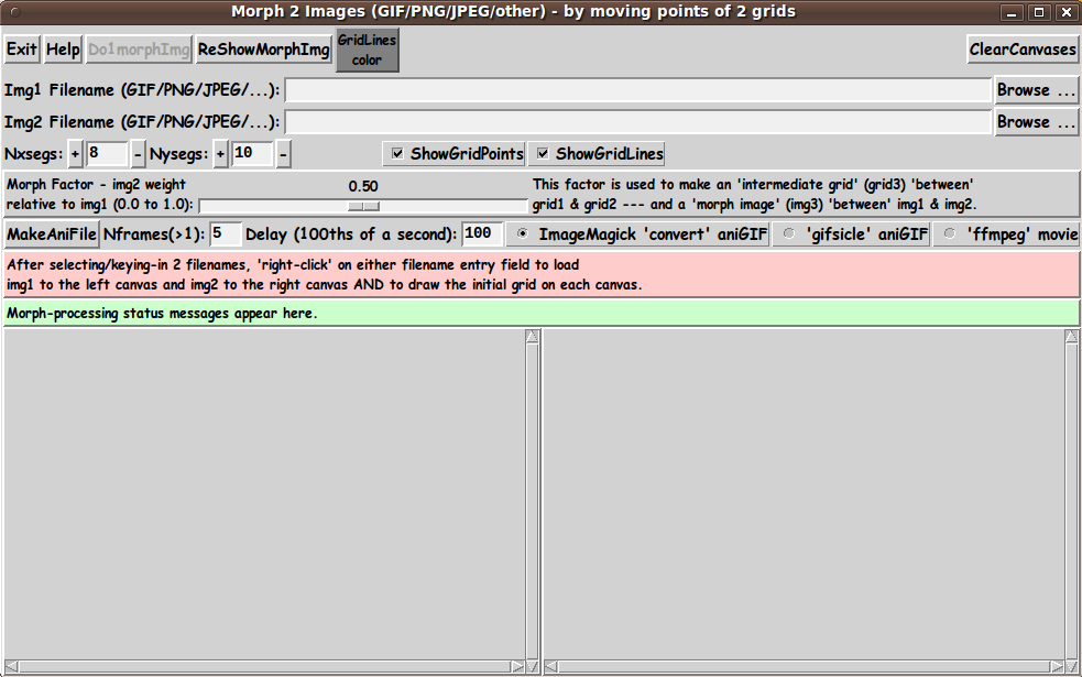
Note that there are two entry fields in which to set the parameters 'Nxsegs' and 'Nysegs' that control the 'fineness' of the grid.
Also note that there are a couple of 'label' widgets across the middle of the GUI --- one label for giving a brief guide on how to load an image to the canvas (with a grid) --- and one 'status' label to allow for communicating to the user how the warp processing is going.
When the user clicks on the 'Do1MorphImg' button, a new window pops up, containing the morphed image and the 'intermediate' grid that was used to make it --- as seen in the following image. The morphed image is usually made within 10 seconds.
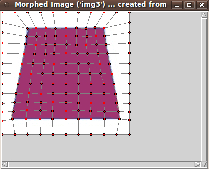
By clicking on the 'MakeAniFile' button, the user can make an animation --- usually within 60 seconds.

Messages in the status frame of the GUI provide the user information on the frame being processed.
---
TYPICAL SEQUENCE OF OPERATIONS WITH THE GUI
STEP 1:
Specify the 2 image files 'to be morphed'. This is most conveniently done with the 'Browse...' buttons on the GUI.
STEP 2:
As indicated in a brief 'guide' on the GUI, the user can 'right-click' (with mouse-button-3) on either filename entry field to cause the two image files to be read and their images shown on the two canvases.
Alternatively, use the 'Return' key on either filename entry field to cause the load-and-display.
STEP 3:
The 'fineness' of the grid can be set via 'Nxsegs' and 'Nysegs' entry fields on the GUI --- which specify the number of grid 'segments' in the x and y directions.
The grid consists of (Nxsegs + 1) times (Nysegs + 1) points. For example, if Nxsegs = 20 and Nysegs = 10, there are 21 x 11 = 231 points in each of the 2 rectangular grids --- and 20 x 10 = 200 rectangles.
(Also 2 * (20 x 10) + 20 + 10 = 430 lines are drawn in the grids.)
You can button1-Press-and-Hold on the '+' and '-' buttons beside the Nxsegs and Nysegs entry fields to change the numbers rather rapidly --- but not so rapidly that they advance more than one unit at a time.
Or you can simply enter numbers in those two fields. Then, like the filename entry field, 'right-click' (mouse-button3-release) or use the Return key to cause the new segments number(s) to be applied. Two new grids will be built on the 2 canvases.
STEP 4:
The user moves one or more grid points, by clicking on either canvas near a grid-point and dragging the grid-point with mouse-button-1.
To help associate points of grid1 with corresponding points of grid2, when the user moves the pointer over a point of either grid, both that point and the corresponding point on the other grid are changed to a new color. This makes it possible to deal with quite dense grids.
When done moving a set of grid points on img1 and img2, click on the 'Do1morphImg' button to cause a 'morph image' to be created, corresponding to the current 'morph factor' setting of the 'scale' widget.
The 'morph image' (img3) will be shown in a popup window in a 3rd scrollable canvas. The 'intermediate deformed grid' that was used to make 'img3' may be hidden or shown on img3.
---
Repeat these steps as needed to get a suitable 'intermediate' image between img1 and img2.
Image capture options are described below --- 'manually' for single images or 'automatic' creation of animation files.
---
CAPTURING AND USING THE WARPED IMAGE:
A SCREEN/WINDOW CAPTURE UTILITY (like 'gnome-screenshot' on Linux) can be used to capture the 'img3' window image in a PNG file, say.
Note that you can use the 'ShowGridPoints' and 'ShowGridLines' checkbuttons on the GUI to turn off the display of the grid on 'img3', before doing an image capture.
If necessary, an image editor (like 'mtpaint' on Linux) can be used to crop the window-capture image. The image could also be down-sized --- say, to make a smaller image suitable for a web page or an email. And the image could be converted from PNG to GIF or JPEG --- for example, by using the image editor or the ImageMagick 'convert' command.
MAKING AN ANIMATED GIF FILE: (or movie file)
Note that one could 'manually' make a sequence of 'morph images' which could be used to make an animated GIF. For example:
One could make 'morph images' for 'morph factors' 0.2, 0.4, 0.6, and 0.8 and capture the 'morph image' corresponding to each 'morph factor'.
Then --- after image editing (cropping or whatever) and image conversion (to GIF, say, if necessary) --- the set of captured-and-processed images, along with the original 2 images, could be combined to make an animated-GIF file --- using a program like ImageMagick 'convert' or 'gifsicle'.
Example ImageMagick 'convert' command:
convert -delay 150 -loop 0 file1 file2 file3 file4 file5 output_ani.gif
where the delay time of 150 is in 100ths of seconds, giving an inter-image wait time of 1.5 seconds. The parameter '-loop 0' indicates that the animated-GIF file should be played indefinitely, rather than stopping after a finite number of cycles.
Alternatively, the sequence of images could be used to make a movie file with a program such as 'ffmpeg' --- with a command like:
ffmpeg -qscale 5 -r 2 -b 9600 -i img%d.png movie.mp4
---
To make it easy for the user to make an animated-GIF (or movie) file, the GUI has a 'MakeAniFile' button.
After the user sets up the warped grids on img1 and img2, the user can SIMPLY click on the 'MakeAniFile' button.
'Underneath the covers', this utility makes 'Nframes' 'morph image' files in a temporary directory --- where 'Nframes' can be specified by the user, in an entry field next to the 'MakeAniFile' button.
By default, this utility uses the ImageMagick 'convert' command to make an animated GIF from the sequence of 'morph image' files that were automatically generated. The 'convert' command uses the 'Delay' parameter on the GUI to determine the length of time each image is displayed.
Alternatively, the user can use the 'gifsicle' command by changing the radiobuttons setting on the GUI.
OR, the user can choose to use the 'ffmpeg' command to make a movie file.
So that the user does not have to navigate to the temporary directory to see the files, the animated GIF is IMMEDIATELY shown to the user in animated mode.
If ImageMagick 'convert' was used, the animated-GIF file is shown with the ImageMagick 'animate' command.
If 'gifsicle' was used, the animated-GIF file is shown with the 'gifview' command, which often comes with 'gifsicle'.
If 'ffmpeg' was used, the movie file is shown with a movie player such as the 'mplayer' command. The user can change the player being used. See the 'make_aniFile' proc in the script.
(Any of these display programs could be changed by a simple change in the 'make_aniFile' proc of the script.)
If the user thinks that the animated file is usable, the user can navigate to the temporary directory (defaulted to /tmp) and find the '_ani.gif' or '.mp4' file there. Move it and/or rename it.
THE CODE
Below, I provide the Tk script code for this 'morph-2-images' utility.
I follow my usual 'canonical' structure for Tk code for this Tk script:
  0) Set general window & widget parms (win-name, win-position,
     win-color-scheme, fonts-for-widgets, widget-geometry-parms,
     text-array-for-labels-etc, win-size-control).

  1a) Define ALL frames (and sub-frames, if any).
  1b) Pack   ALL frames and sub-frames.

  2) Define & pack all widgets in the frames, frame by frame.
              Within each frame, define ALL the widgets.
              Then pack the widgets.

  3) Define keyboard and mouse/touchpad/touch-sensitive-screen action
     BINDINGS, if needed.

  4) Define PROCS, if needed.

  5) Additional GUI initialization (typically with one or more of
     the procs), if needed.
This Tk coding structure is discussed in more detail on the page A Canonical Structure for Tk Code --- and variations.
This structure makes it easy for me to find code sections --- while generating and testing a Tk script, and when looking for code snippets to include in other scripts (code re-use).
I call your attention to step-zero. One thing that I started doing in 2013 is use of a text-array for text in labels, buttons, and other widgets in the GUI. This can make it easier for people to internationalize my scripts. I will be using a text-array like this in most of my scripts in the future.
EXPERIMENTING WITH THE GUI
As in all my scripts that use the 'pack' geometry manager (which is all of my 100-plus scripts, so far), I provide the four main pack parameters --- '-side', '-anchor', '-fill', '-expand' --- on all of the 'pack' commands for the frames and widgets.
That helps me when I am initially testing the behavior of a GUI (the various widgets within it) as I resize the main window.
I think that I have used a pretty nice choice of the 'pack' parameters. The label and button and checkbutton widgets stay fixed in size and relative-location if the window is re-sized --- while the filename entry widgets expand/contract horizontally whenever the window is re-sized horizontally.
And the 2 canvases expand both horizontally and vertically when the window is resized.
For example, if the user clicks on the Maximize button of the window, the window-manager expands the window to screen-size --- and the filename entry fields expand to maximum size horizontally, and the 2 canvases expand to a maximum size both horizontally and vertically.
You can experiment with the '-side', '-anchor', '-fill', and '-expand' parameters on the 'pack' commands for the various frames and widgets --- to get the widget behavior that you want.
___
Additional experimentation: You might want to change the fonts used for the various GUI widgets. For example, you could change '-weight' from 'bold' to 'normal' --- or '-slant' from 'roman' to 'italic'. OR change font families.
In fact, you may NEED to change the font families, because the families I used may not be available on your computer --- and the default font that the 'wish' interpreter chooses may not be very pleasing.
I use variables to set geometry parameters of widgets --- parameters such as border-widths and padding. And I have included the '-relief' parameter on the definitions of frames and widgets. Feel free to experiment with those 'appearance' parameters as well.
If you find the gray 'palette' of the GUI is not to your liking, you can change the value of the RGB parameter supplied to the 'tk_setPalette' command near the top of the code.
---
Note that the 'GridLines Color' button on the GUI calls on an RGB-color-selector-GUI script to set the color of grid lines. You can make that RGB-color-selector script by cutting-and-pasting the code from the page A non-obfuscated color selector GUI on this site.
SOME FEATURES IN THE CODE
That said, the code is below --- with plenty of comments to describe what most of the code-sections are doing.
You can look at the top of the PROCS section of the code to see a list of the procs used in this script, along with brief descriptions of how they are called and what they do.
The procs are similar to the ones used in the 'tkImgGridWarp' script, with some additions and changes.
   'get_img1_filename'      - called by the 'Browse...' button beside
                              the entry field for the image1 file.

   'get_img2_filename'      - called by the 'Browse...' button beside
                              the entry field for the image2 file.

   'get_chars_before_last'  - called by procs 'get_img*_filename' and
                              'checkFile_convertToGIF'.

   'checkFile_convertToGIF' - called by proc 'get_img_filename'.

   'load_2files_to_canvases'   - called by button3-release or <Return> on
                                 a filename entry field.

 The following procs are called by 'load_2files_to_canvases', to get the party started.

   'load_photoID1'           - called by proc 'load_2files_to_canvases'.
   'load_photoID2'           - called by proc 'load_2files_to_canvases'.

   'set_canvas1and2_sizeANDcenter'  - called by proc 'load_2files_to_canvases'.

   'put_img1_on_canvas1'     - called by proc 'load_2files_to_canvases'.
   'put_img2_on_canvas2'     - called by proc 'load_2files_to_canvases'.

   'initialize_grid1and2_arrays' - called by proc 'load_2files_to_canvases'.

   'draw_grid1'             - called by proc 'load_2files_to_canvases'.
   'draw_grid1_points'      - called by the 'draw_grid1' proc.
   'draw_grid1_lines'       - called by the 'draw_grid1' proc.

   'draw_grid2'             - called by proc 'load_2files_to_canvases'.
   'draw_grid1_points'      - called by the 'draw_grid1' proc.
   'draw_grid1_lines'       - called by the 'draw_grid1' proc.

  Note that if one wants to RESTART with a new image --- by changing the
  image data in the named image file, or by switching to a new image filename
  --- the RESTART can be effected by running the above procs again ---
  by simply calling the 'load_2files_to_canvases' proc.

  We should also consider which of the above procs should be rerun
  when the x,y grid-segments entries are changed. Note that changing
  x,y grid-segments requires rerunning the last 3 procs ---
  'initialize_grid1and2_arrays' and 'draw_grid1' and 'draw_grid2'.

 These line-redrawing procs are called in following 'move_point' procs.

   'delete_lines1_at_ij'    - called by proc 'move_point1End', to delete
                              the 4 or 3 lines connected to the moved grid-point.

   'delete_lines2_at_ij'    - called by proc 'move_point2End', to delete
                              the 4 or 3 lines connected to the moved grid-point.

   'redraw_lines1_at_ij'    - called by proc 'move_point1End', to redraw
                              the 4 or 3 lines connected to the moved grid-point.

   'redraw_lines2_at_ij'    - called by proc 'move_point2End', to redraw
                              the 4 or 3 lines connected to the moved grid-point.

 The following 6 procs handle moving a grid-point.

   'move_point1Select'  - called by a button1-press   binding on a point-tag of canvas1.
   'move_point1'        - called by a button1-motion  binding on canvas1.
   'move_point1End'     - called by a button1-release binding on a point-tag of canvas1.

   'move_point2Select'  - called by a button1-press   binding on a point-tag of canvas2.
   'move_point2'        - called by a button1-motion  binding on canvas2.
   'move_point2End'     - called by a button1-release binding on a point-tag of canvas2.

 The following 4 procs handle hi-liting of corresponding points on canvas1 & canvas2.

   'canvas1_point_enter' - called by button1-enter binding on a point-tag of canvas1.
   'canvas1_point_leave' - called by button1-leave binding on a point-tag of canvas1.
   'canvas2_point_enter' - called by button1-enter binding on a point-tag of canvas2.
   'canvas2_point_leave' - called by button1-leave binding on a point-tag of canvas2.

 The following 3 procs create 'IDimg3'/'IDimgANI' based on the 'intermediate grid', grid3,
 which is a morph-factor-weighted linear interpolation of the corresponding points
 of grids 1 and 2.

   'set_grid3'         - called by the 'morph_over_grid' proc and the
                                       'make_aniFile'    proc below.

 'morph_over_grid'     - called by 'Do1morphImg' button. Calls the 'morph_inQuad'
                         proc in a loop.

   'morph_inQuad'      - called by the 'morph_over_grid' and 'make_aniFile' procs.

                         This proc is called in 'morph_over_grid' and 'make_aniFile'
                         for each 'grid3' quadrangle.

                         At each quadrangle of grid3, this 'morph_inQuad' proc
                         fills in pixel-colors of 'IDimg3'/'IDimgANI' in the 2 triangles
                         of the grid3 quad --- 'barymetrically'. See the
                         'fill_grid3_triangle_with_corners' proc for details.

                         See a rough diagram of the quadrangles and their triangles
                         in comments in this code.

                         For a given one of the triangles,
                         the 'barymetric morph' is done by a 'barymetric mapping' between
                         the 'intermediate triangle' of grid3 and the corresponding two
                         triangles of grid1 and grid2 on IDimg1 and IDimg2.

                         The pixels in the 'intermediate triangle' are 'colored' according
                         to a weighted-average of the 2 corresponding pixels in IDimg1 and
                         IDimg2.

  'fill_grid3_triangle_with_corners'  - called by the 'morph_inQuad' proc,
                                        to handle the barymetric color-mapping
                                        for each of the 2 triangles in the quad.
                                        Called once for each triangle.

  'min3'           - called by proc 'fill_grid3_triangle_with_corners'

  'max3'           - called by proc 'fill_grid3_triangle_with_corners'

  Here are some 'utility' procs:

  'popup_img3'              - called by the 'ReShowMorphImgAndGrid' button.

  'draw_grid3'              - called by the 'popup_img3' proc.
  'draw_grid3_points'       - called by the 'draw_grid3' proc.
  'draw_grid3_lines'        - called by the 'draw_grid3' proc.

  'make_aniFile'           - called by the 'MakeAniFile' button.

 The following 4 procs handle the '+' and '-' buttons beside the
 Nxsegs and Nysegs entry fields.

   'incr_nxsegs'       - called by button1-press binding on Nxsegs '+' button
   'decr_nxsegs'       - called by button1-press binding on Nxsegs '-' button
   'incr_nysegs'       - called by button1-press binding on Nysegs '+' button
   'decr_nysegs'       - called by button1-press binding on Nysegs '-' button

   'reload_grid1and2'  - called by button3-release or Return bindings on the
                         Nxsegs and Nysegs entry fields.

 The following 2 procs handle the Show Points/Lines checkbuttons.

 'hide-show_grid_points' - called by button1-release binding on the points checkbutton
 'hide-show_grid_lines'  - called by button1-release binding on the lines checkbutton

 Other utility procs:

 'clear_canvases'          - called by the 'ClearCanvases' button

 'set_gridlines_color'     - called by the 'GridLinesColor' button

 'update_linecolor_button' - called by proc 'set_gridlines_color' and in the
                                    additional-GUI-initialization section at
                                    the bottom of this script.

   'popup_msgVarWithScroll' - used to show messages to the user, such as
                              the HELPtext for this utility via the 'Help' button.
---
Modularity of procs
One of the trickiest things about this GUI involved finding a way to break up the necessary operations into a 'modular' form in the procs --- so that the groups-of-operations would support the various user-actions that might be needed via the GUI widgets.
Comments at the top of the code indicate how I outlined the sequence of operations to be implemented and how I grouped those operations into separate procs.
Even if it is necessary to change, somewhat, the way the operation-groups are performed in response to 'events' on the widgets of the GUI, the 'granularity' of the modular break-down of the operations into procs will probably serve to facilitate a relatively easy change to accomodate the necessary operations triggered by any particular widget-event.
---
JPEG and PNG (and other non-GIF image formats)
Another challenge was to be able to handle JPEG and PNG files as well as GIF files --- without requiring the user to install a '3rd party' Tk-extension to handle reading JPEG files --- or to install Tk 8.6 to handle reading PNG files.
I settled on using the 'exec' command to issue the ImageMagick 'convert' command.
Code fragment in proc 'checkFile_convertToGIF':
set RETcode [catch {exec convert "$INfilename" -colors 256 "$tempFilename"} CatchMsg]where 'tempFilename' contains a name that ends with '.gif'.
In fact, the proc 'checkFile_convertToGIF' includes an 'exec' of the 'file' command to determine if the $INfilename file is a GIF file --- via use of the Tcl 'string match' command.
If the file is determined to be a GIF file, then 'convert' is not used. But, for any other file, the file is converted to a GIF file.
So this utility will actually warp any of the 100-plus types of image file supported by the ImageMagick 'convert' command --- by converting such files to a new '.gif' file. Reference: http://www.imagemagick.org/script/formats.php
So this utility will convert PGM (Portable Gray Map), PPM (Portable Pixel Map), TIFF (Tagged Image File Format), TGA (Targa), XWD (X Window Dump) and other types of image files to '.gif' files --- and do the warp with those GIF files.
---
High-lighting grid points
In the first grid-deformation tests I did after getting the GUI up, I found that it was hard to find, for a given grid-point on one grid, the corresponding grid point on the other grid.
The 4 'leave and enter' procs --- 'canvas1_point_enter', 'canvas1_point_leave', 'canvas2_point_enter', 'canvas2_point_leave' --- contain the code to highlight pairs of grid points. These procs use 3 'lookup' arrays that map i,j grid point indexes to Tk-point-IDs and vice versa.
I am rather pleased with those procs, because I devised them 'from scratch'. I did not have an example to go by.
---
Handling huge images
To be able to scroll huge images, a '-scrollregion' parameter is used to configure the (scrollable) canvases --- in proc 'set_canvas1and2_sizeANDcenter'.
There are probably other noteworthy 'features' of the code that could and should be mentioned here.
In fact, it would probably be helpful to provide some 'lessons learned' about
** the 'move_point' procs and their bindings to tag or canvas
** the need to keep the grid-points 'above' the grid-lines, so that the grid-lines do not interfere with selecting a grid-point to move.
There are a few comments in the code on these issues, but they deserve a little more discussion. However, this 'features of the code' section is long enough as is. Enough for now.
It is my hope that the copious comments in the code will help Tcl-Tk coding 'newbies' get started in making GUI's like this.
Without the comments, potential young Tcler's might be tempted to return to their iPhones and iPads and iPods --- to watch videos of people literally 'knocking themselves out' --- trying to break bricks and plywood on their heads.
Code for Tk script 'wheeeMorph.tk' :
#!/usr/bin/wish -f
##
## SCRIPT: wheeeMorph.tk
##
## PURPOSE: This Tk GUI script implements the following features:
##
## 1) The GUI allows the user to select 2 image files ---
## GIF or PNG or JPEG or other.
##
## 2) The GUI allows the user to read the 'pixel data' from the
## 2 files and display the 2 images on 2 side-by-side Tk
## (scrollable) canvases within the GUI window.
##
## 3) The GUI allows the user to specify a grid of points-and/or-lines
## over each of the two images. The two grids will initially have
## rectangular 'cells' in a rectangular boundary. The grids will
## be deformable. The two grids will always have the same number
## of horizontal and vertical 'segments'.
##
## 4) In this implementation of this 'morphing' utility,
## the INTERIOR grid-points of the 2 grids are movable.
## And ... the grid points on the OUTER EDGE of the 2 grids
## are 'SLIDABLE' ALONG THE 4 EDGES, but NOT MOVEABLE 'INWARD'
## or 'OUTWARD'.
##
## This will handle situations like face-head images with 2 different
## neck sizes at the bottom of the 2 images. The ability to 'slide'
## the edge grid points will allow for good morphing from a
## thick-neck to a skinny-neck, for example, where the necks are
## cut off along the bottom of the 2 images.
##
## (A future enhancement could allow for pulling the 'edge' grid
## points 'INWARD'. However, the grid-handling code may become a bit
## more complex and one would probably want to offer an option to
## set a background color or image to fill the exposed part of
## the original rectangular areas. So it might be good to keep this
## script intact and make a new 'wheeeMorph_withInwardMoveableEdges.tk'
## script.
##
## An even more enhanced script would allow for a margin (solid color
## or background image) around the 2 images and allow for 'pushing' the
## 'edge' grid points 'OUTWARD' as well as 'pulling' them inward ---
## a 'wheeeMorph_withFullyMoveableEdges.tk' script.)
##
## 5) A 'scale' widget on the GUI, with values between 0.00 and 1.00 ---
## for a 'morph factor' --- can be set to determine the grid-point
## locations of an 'intermediate grid', determined from the grid-point
## locations of the 2 user-deformed grids on image1 and image2.
##
## A 'Do1morphImg' button on the GUI can be used to generate the
## 'intermediate grid' and then an 'intermediate image' --- which is
## determined from the original 2 images and the 2 'user-deformed'
## grids on the 2 images.
##
## Thus, with the 'morph-factor' scale widget and the 'Do1morphImg' button,
## the user can 'manually' build a sequence of 'morph images' that
## transition from image1 to image2. These images could be captured
## and used to make an animated GIF file or movie file. HOWEVER ...
##
## 6) A main function of this script will be to offer an 'Nframes' entry
## widget and a 'MakeAniFile' button with which the user can
## 'automagically' make a sequence of image files, in a 'work directory',
## that transition ('morph') from image1 to image2 --- and this script
## will 'automagically' make an animated GIF-file or movie-file for
## the user --- using a program like ImageMagick 'convert' to make
## an animated GIF-file or a program like 'ffmpeg' to make an
## animated movie-file.
##
########################################
## SOME SPECIAL FEATURES OF THIS UTILITY: (and details about its processing)
##
## ****************************
## SIZE-AND-USE OF THE 2 IMAGES:
## ****************************
##
## NOTE: To make it easy for the user, WE DO NOT REQUIRE THAT
## THE TWO IMAGES TO BE THE SAME SIZE. This helps the user by
## not requiring the user to do some detailed image editing to
## get 2 image files of exactly the same size --- the same width
## and height in pixels.
##
## However, we DO want to morph between 2 images of the same size, because
## the ultimate aim of this utility is to make an animated GIF/movie file,
## whose (rectangular) frames are all the same size --- made without
## 'zooming' any of the images up or down.
##
## SO ... this utility will perform the following operations.
## a) Determine the greater of the 2 widths and 2 heights of the 2 images
## and make the 2 scrollable canvases the same size --- with width
## 'MAX-WIDTH-img1-img2' and height 'MAX-HEIGHT-img1-img2'.
## Determine the center coordinates of the 2 canvases.
## b) CENTER the two images in the 2 canvases.
## c) Determine the UPPER-LEFT CORNER location on canvas1 and canvas2
## and the WIDTH and HEIGHT of a 'common overlay area' of each image.
## Note that the size of that area will be the 'MIN-WIDTH' and 'MIN-HEIGHT'
## of the 2 original images. Since we are allowing the 2 images to be
## (slightly) different in size, we also must get the location of the
## UPPER-LEFT CORNER of the 'common overlay area' on image1 and image2
## --- for later retrieval of pixel colors on image1 and image2.
## d) 'Draw' the same sized grid on each canvas (over each image) --- so that
## the 2 grids are located on the 'common overlay area' of the 2 images.
## e) Use the 'common overlay area' of each image to make the
## 'intermediate image' for an given 'morph-factor' ( 0.0 to 1.0).
## We will refer to that 'intermediate image' as 'img3',
## and we will call the 'intermediate grid' that was used to make
## img3 'grid3'. The details of this step are outlined below.
##
## In short, this utility will center and 'crop' the two images automatically
## for the user, in-memory, so that the user does not have to do a lot of
## preliminary image manipulation to start with two image files with images of
## exactly the same size (width and height in pixels).
##
## *****************************
## SIZE-AND-USE OF THE TWO GRIDS: (and a 3rd 'intermediate grid')
## *****************************
##
## Since the 'common overlay areas' on the two images are the
## same size, the two grids placed on that area of the 2 images
## will be the same size.
##
## Initially, the 2 grids on image1 and image2 are identical, except that
## they are horizontally displaced from each other, in 2 side-by-side canvases.
## Initially the 2 grids will have rectangular 'cells' --- before they are
## deformed by the user.
##
## The grids on the 2 images have the same number of rows and columns
## --- of points and lines.
##
## If the user moves grid-point 'i,j' on one image to a key feature
## (like the left-corner of a mouth on a face picture), then the user would
## (typically) move the corresponding 'i,j' grid-point on the other image
## to a corresponding feature (like the left-corner of a mouth on a SECOND
## face picture).
##
## When the user is done moving a set of corresponding grid points on the
## 2 images, the user can click on a 'Do1morphImg' button to:
##
## 1) create the 'intermediate grid', 'grid3', which is a 'weighted
## linear interpolation' of the 2 user-warped grids, 'grid1' and 'grid2',
## and
## 2) create a new image, 'img3' (the size of the 'common overlay area') by
## mapping quadrangles of 'grid3' back to quadrangles of user-deformed
## 'grid1' and user-deformed 'grid2', where 'grid1' and 'grid2' are
## deformations of the ORIGINAL, rectangular-celled grids placed
## on image1 and image2.
##
## Each of the pixels of 'img3' is generated as a weighted average of
## the 2 pixel colors taken from 'corresponding' pixels of image1 & image2.
## The same 'morph factor' that was used to create 'grid3' is used to
## do the weighting of the 2 pixel colors.
##
## More detail (on how the quadrangles are mapped using 2 triangles
## within each quadrangle and by using barymetric coordinates on
## the triangles) is in descriptions far below --- of the procs used.
##
## In case the morph processing drags on for a while, some status
## messages are posted in a status line on the GUI, to indicate which
## grid point area (index i,j) --- of the 'common overlay area' ---
## is currently being processed in the 3 images image1, image2, and 'img3'.
##
## The new 'morphed' image is shown in a popup window that contains
## a 3rd (scrollable) canvas --- along with the points/lines that
## make up the 'intermediate grid' that was used to make the 'morphed' image.
## In other words, the popup window shows 'img3' and optionally shows 'grid3'
## on top of 'image3'. The grid is hide-able, for image capture purposes.
##
## ************************
## CHANGING GRID PARAMETERS: (rows and columns)
## ************************
##
## The user can specify, via entry widgets on the GUI, the number of
## horizontal and vertical 'segments' in the 2 grids on image1 and
## image2. We refer to these segment numbers as 'Nxsegs' and 'Nysegs'.
##
## ********************
## CHANGING THE GRID(S):
## ********************
##
## After setting the values 'Nxsegs' and 'Nysegs' as desired, the user can move
## corresponding points of the 2 rectangular grids to 'features' on the
## 2 images. Then click on the 'Do1morphImg' button to perform a morph based
## on the 2 warped grids --- and the current value of the 'morph factor'.
##
## ************************
## CAPTURING MORPHED IMAGES:
## ************************
##
## The user can hide the grid points and/or lines on the new
## 3rd image, 'img3' --- typically to prepare for taking a 'snapshot'
## of the 'morphed image'.
##
## A 'ReShowMorphImg' button allows for 're-showing' the
## 'intermediate' morphed image (img3) in a canvas in a popup window ---
## in case the user has closed the 'morph-result' window. The user may
## need to be able to 'retrieve' that popup window --- to be able to
## capture the morphed image.
##
## *********************************
## MAKING ANIMATED GIF's (or movies):
## *********************************
##
## By doing screen/window captures of a sequence of morphed images,
## the user can *MANUALLY* make an animated GIF (or a movie file) with the
## sequence of images --- generated from image1 and image2 by using a
## sequence of 'morph factors' --- for example, 0.2, 0.4, 0.6, and 0.8.
##
## A 'MakeAniFile' button --- along with 'Nframes' and 'Delay'-time
## parameters in entry fields --- are available on the GUI to *AUTOMATE* the
## process of making an animated-GIF (or movie) file --- from the 2 images
## and the 2 warped grids on the 2 images. The 'Nframes' number is used
## to generate a sequence of EQUALLY-SPACED 'morph factors' between
## 0.0 and 1.0. The action of the 'Do1morphImg' button is automatically
## repeated for each of the 'morph factors' --- to get a sequence of
## image files that are used to make an animated-GIF (or movie) file.
##
## *****************
## RE-STARTING FRESH:
## *****************
##
## If things get confusing, the user can click on a 'ClearCanvases'
## button to clear the 2 original image canvases. Then the user can
## reload the 2 image files to the 2 canvases and start fresh.
##
##+#########################
## PLANNED LAYOUT OF THE GUI:
##
## -----------------------------------------------------------------------------
## Morph 2 Images - (GIF/JPEG/PNG/other) - by moving interior points of 2 grids
## [window title]
## -----------------------------------------------------------------------------
##
## {Exit} {Help} {Do1morphImg} {ReShowMorphImg} {ClearCanvases}
##
## Img1 Filename (GIF/PNG/JPEG/...): ___________________________________ {Browse...}
## Img2 Filename (GIF/PNG/JPEG/...): ___________________________________ {Browse...}
##
## Nxsegs: {+}____{-} Nysegs: {+}____{-} X ShowGridPoints X ShowGridLines
##
## Morph Factor (0.0 to 1.0): <-------------O--------------> to make an 'intermediate grid' and a 'morph image'
## [The text string above is in a label widget, with small font.]
##
## {MakeAniFile} Nframes(>1) ___ Delay (100ths of a second): ___ O ImageMagick 'convert' O 'gifsicle' O 'ffmpeg'
##
## After selecting/keying-in 2 filenames, 'right-click' on either filename entry field to
## load each image to its canvas AND to draw the initial grid on each canvas.
## [This guide is in a label widget.]
##
## Morph-processing status messages appear here.
## [This status-line is in a label widget.]
## -------------------------------------- ------------------------------------------
## | A | A
## | | | |
## | | | |
## | 'Canvas1' for displaying 'image1' | | 'Canvas2' for displaying 'image2' |
## | and its deformable grid, 'grid1'. | | and its deformable grid, 'grid2'. |
## | | | |
## | | | |
## | | | |
## | | | |
## | V | V
## <------------------------------------> <---------------------------------------->
##
## [The 'intermediate grid', 'grid3', and the 'morphed image', 'img3' --- generated
## based on a 'barymetric' mapping of grid3 back to original, rectangular grids 1 and 2
## --- are shown in a popup window containing a scrollable canvas, 'canvas3'.]
##
## SKETCH CONVENTIONS for this GUI sketch:
##
## SQUARE-BRACKETS indicate a comment (not to be placed on the GUI).
## BRACES indicate a Tk 'button' widget.
## A COLON indicates that the text before the colon is on a 'label' widget.
## UNDERSCORES indicate a Tk 'entry' widget.
## CAPITAL-X indicates a Tk 'checkbutton' widget.
## CAPITAL-O indicates a Tk 'radiobutton' widget (if any).
##
## A LINE (HYPHENS or VERTICAL-BARS) WITH AN 'ARROW-HEAD' AT EACH END indicates a Tk 'scale' widget.
##
## A combination of VERTICAL-BAR CHARACTERS AND HYPHEN (or UNDERSCORE) CHARACTERS,
## that outline a RECTANGULAR SHAPE, are used to indicate either a Tk 'listbox' or
## a Tk 'canvas' widget or a Tk 'text' widget.
##
## SCROLL-BAR 'ARROW-HEADS' (for a 'listbox', 'canvas', or 'text' Tk widget)
## are drawn as follows:
##
## UP ARROW-HEAD is drawn with a CAPITAL-A.
## DOWN ARROW-HEAD is drawn with a CAPITAL-V.
## LEFT ARROW-HEAD is drawn with a LESS-THAN sign.
## RIGHT ARROW-HEAD is drawn with a GREATER-THAN sign.
##
##
## UP-and-DOWN ARROW-HEADS at the right/left of the box shape indicate a VERTICAL SCROLL-BAR there.
##
## LEFT-and-RIGHT ARROW-HEADS at the bottom/top of the box shape indicate a HORIZONTAL SCROLL-BAR there.
##
## The arrow-heads on a horizontal scrollbar are joined by hyphens, rather than underscores.
##
##+##################
## GUI WIDGET SUMMARY:
##
## This GUI will contain about:
##
## 11 'button' widgets
## 9 'label' widgets
## 6 'entry' widgets
## 1 'scale' widgets
## 2 'checkbutton' widgets
## 2 'radiobutton' widgets
## 2 'canvas' widgets (with x-y scrollbars)
## 0 'listbox' widgets
## 0 'text' widgets
##
##+################################################################
## MATHEMATICAL ('BARYMETRIC') METHOD USED to morph the 2 images:
##
## Image-morphing is done, in this script, via barymetric coordinates in
## TRIangles within 4 rectangles/quadrangles around each INTERIOR
## grid point of an 'intermediate/averaged warped grid'.
##
## The 'intermediate grid' is obtained by using the 'morph factor'
## (between 0.0 and 1.0) to get the i,j-th grid point of the
## 'intermediate grid' by a 'weighted linear interpolation' between the
## i,j-th point of deformable grid1 and the i,j-th point of deformable
## grid2.
##
## So that we use the same triangle configuration around each
## grid point, we adopt the following configuration of triangles
## in the 4 quadrangles around each INTERIOR grid point.
##
## (+ denotes a grid point)
##
## M-1,N-1 M,N-1 M+1,N-1
## +-------+-------+
## | /| /|
## | / | / |
## | / | / |
## |/ M,N|/ |
## M-1,N +-------+-------+ M+1,N
## | / | /|
## | / | / |
## | / | / |
## |/ |/ |
## +-------+-------+
## M-1,N+1 M,N+1 M+1,N+1
##
## (We arbitrarily choose to make the diagnals go upward
## to the northeast, rather than to the northwest.
##
## This triangulation gives a certain 'bias' to the morphing
## process, but most visual 'bias-effects' can be minimized
## by the user choosing a fine-enough grid.
##
## An advantage to this consistent triangulation pattern
## around each interior grid point is that the program logic
## becomes less complex than with a 'fancier' triangulation.)
##
## When an INTERIOR grid point M,N is moved, 6 of these
## 8 triangles are moved. (By 'moved', we mean that the xy
## coordinates of at least one of the 3 vertices in a
## moved-triangle changed.)
##
## Only the upper-left and the lower-right triangles are
## left unmoved. Their 3 vertices do not move when M,N moves.
##
## If the point M,N is moved, the shape of 6 triangles changes
## --- in the 4 quadrangles surrounding grid-point M,N.
##
## We will assign 'i,j' ID's to the rectangles/quadrangles, like we have
## to the grid-points. We choose to use the 'i,j' ID of the lower-right
## grid-point of a quadrangle to be the ID of the quadrangle.
##
## So, in the diagram above:
## - the upper-left quadrangle has ID 'M,N'
## - the upper-right quadrangle has ID 'M+1,N'
## - the lower-left quadrangle has ID 'M,N+1'
## - the lower-right quadrangle has ID 'M+1,N+1'
##
## If the ID's of the grid-points go from
## 0 to Nxsegs and 0 to Nysegs,
## then the ID's of the quadrangles go from
## 1 to Nxsegs and 1 to Nysegs.
##
## Note that if grid-point M,N is moved, then we have to
## consider doing morping-processing in the 4 quadrangles
## around M,N --- the quadrangles with QUADRANGLE-ID's:
## 'M,N' 'M+1,N' 'M,N+1' 'M+1,N+1'
##
## And we have to do morphing processing on at least 6 of the
## 8 triangles in those 4 quadrangles.
##
## If only grid-point M,N were moved and none of its neighboring grid
## points are moved (in particular, if M-1,N-1 and M+1,N+1 are not moved),
## then 2 of the triangles in the 4 quadrangles around point M,N
## do not move, and no morphing processing would have to be done on
## those 2 triangles. BUT ...
##
## Note that since other grid-points around M,N will (in general)
## be moved --- even those other 2 triangles may have been
## moved and will (in general) have to be processed.
##
##+######################################
## ARRAYS FOR THE GRID POINT COORDINATES:
## ('grid1', 'grid2', 'grid3')
##
## In this code,
## the current location (in pixels, on the 3 scrollable canvases) of the
## grid points of THREE grids is stored in 3 pairs of arrays with indices
## in the form the string "$i,$j":
##
## - aRgrid1Xpx($i,$j) and aRgrid1Ypx($i,$j)
##
## - aRgrid2Xpx($i,$j) and aRgrid2Ypx($i,$j)
##
## - aRgrid3Xpx($i,$j) and aRgrid3Ypx($i,$j)
##
## --- where i goes from 0 to Nxsegs and j goes from 0 to Nysegs.
##
## (For each grid,
## we use a PAIR of X,Y arrays with a SINGLE numeric value
## for each index "$i,$j" --- rather than a SINGLE array
## with a PAIR of numeric values for each index. This allows
## us to avoid repeatedly using the 'foreach-break' technique
## that is typically used in Tcl-Tk code to extract individual
## numbers from a 'tuple' of numbers.)
##
## The arrays 'aRgrid1' and 'aRgrid2' are used to display (deformable)
## grids on canvas1 and canvas2. The pixel coordinates of each grid
## point is relative to the upper-left corner of the 2 canvases. This
## makes the handling of moving grid points on the 2 canvases, via
## 'move_point' procs, relatively straight-forward. HOWEVER ...
##
## Note that, when determining the color of a pixel for 'img3', that process
## will require the retrieval of the color of points on the 'common overlay area'
## of image1 and imag2 --- and to do that, we will have to ADJUST the coordinates
## of 'grid1' and 'grid2' points to be relative to the top-left corner
## of image1 and image2, rather than using 'grid1' and 'grid2' coordinates
## that are measured relative to the upper-left corner of canvas1 and canvas2.
##
##+########################################
## 'HANDLES' FOR image1, image2, and 'img3':
## (where image1 and image2 do not have to be the same size, yet
## 'img3' is the size of the 'common overlay area' of images 1 and 1.)
##
## To avoid generating a lot of different image 'handles' for the 3
## in-memory images (and to lessen the likelihood of consuming ever more
## memory if many morphs are done in a session), we will create
## 'handles' for the 3 images ONCE with 3 'image create photo' commands.
## We will use these 3 names for the handles:
## 'IDimg1' 'IDimg2' 'IDimg3'
##
## (We might use a 4th 'IDimg3TEMP', say, to make a sequence of images
## in the 'make_aniFile' proc --- rather than using 'IDimg3'.)
##
##+##########################################################
## THE TYPICAL SEQUENCE OF USER-STEPS (and procs) IN MORPHING:
##
## 0) The user selects 2 image files via the 'Browse...' buttons,
## to put the selected image1 filename in the filename1 entry widget
## and put the selected image2 filename in the filename2 entry widget.
##
## IMPLEMENTATION IS VIA PROCS:
## 'get_img1_filename' and 'get_img2_filename'
##
## 1) When the user 'right-clicks' on either filename entry field
## (or uses the Return key), the following sequence of operations
## is performed.
##
## 1a) PROC 'load_photoID1':
## The image data from image-file1 is loaded into the in-memory
## 'photo' image structure called 'IDimg1'.
## The width and height of 'IDimg1' are put in variables.
##
## 1b) PROC 'load_photoID2':
## The image data from image-file2 is loaded into the in-memory
## 'photo' image structure called 'IDimg2'.
## The width and height of 'IDimg2' are put in variables.
##
## 1c) PROC 'set_canvas1and2_sizeANDcenter':
##
## a) The WIDTH AND HEIGHT of 2 (scrollable) canvases is determined by
## the max-width and max-height of the widths/heights from the two
## 'photo' IDs.
## b) This proc also determines the coordinates of the CENTER POINT on
## the 2 canvases --- the 'anchor point' for centering the 2 images
## on the2 canvases.
## c) The max-width and max-height determined in step-a are used to
## set the scroll-region size of canvases 1 and 2.
## The 'scrollregion' allows for handling very large images in
## canvases 1 and 2 --- and the user can scroll to see ALL of
## image1 and image2.
## d) The size (width and height) of the 'common overlay area' of image1
## and image2 is put in variables. The size is simply the min-width
## and min-height of the widths/heights from the two 'photo' IDs.
## e) The canvas coordinates of the upper-left corner of the
## 'common overlay area' of the 2 images is determined for canvases
## 1 and 2. That will be the location of the upper-left point of
## 'grid1' on canvas1 and the location of the upper-left point of
## 'grid2' on canvas2. This 'offset' in the x and y directions is
## simply calculated as
## - half of the (max-width - min-width)
## and
## - half of the (max-height - min-height).
##
## (A background color for the 2 canvases could be applied in this proc.)
##
## 1d) PROC 'put_img1_on_canvas1':
## The image, IDimg1, is put on canvas1 with a canvas
## 'create image' command. The center of the image is placed
## at the center of (scrollable) canvas1.
##
## 1e) PROC 'put_img2_on_canvas2':
## The image, IDimg2, is put on canvas2 with a canvas
## 'create image' command. The center of the image is placed
## at the center of (scrollable) canvas2.
##
## 1f) PROC 'initialize_grid1and2_arrays':
## The 2 pairs of arrays
## 'aRgrid1Xpx' & 'aRgrid1Ypx'
## 'aRgrid2Xpx' & 'aRgrid2Ypx'
## are initialized with grid-point pixel coordinates according to
## a) the 'upper-left' coords of the 'common overlay area' determined
## in the 'set_canvas1and2_sizeANDcenter' proc
## and
## b) the 'common overlay area' size and the value of 'Nxsegs' and
## 'Nysegs' --- which are used to determine the horizontal
## and vertical sizes of the 'rectangular cells'.
##
## Note that we will always load 'grid1' and 'grid2' with
## pixel coordinates relative to the upper-left corner
## of their canvases. If image1 and image2 are the same size, then
## the upper-left corner of the 'grid1' & 'grid2' arrays will be at (0,0).
## If they are not the same size, then not --- that is, the upper left
## corner of the grids will be offset of the 'common overlay area' of
## image1 and image2 from the upper left corner of their canvases.
##
## 1g) PROC 'draw_grid1': (for DEFORMABLE grid1)
## If the 'ShowGridPoints' checkbutton is ON (initially it is),
## grid POINTS are drawn on image1 in canvas1, according to the
## contents of the X,Y arrays denoted by 'aRgrid1'.
## If the 'ShowGridLines' checkbutton is ON (initially it is),
## grid LINES are drawn on image1 in canvas1, according to the
## contents of the X,Y arrays denoted by 'aRgrid1'.
##
## 1h) PROC 'draw_grid2': (for DEFORMABLE grid2)
## If the 'ShowGridPoints' checkbutton is ON (initially it is),
## grid POINTS are drawn on image2 in canvas2, according to the
## contents of the X,Y arrays denoted by 'aRgrid2'.
## If the 'ShowGridLines' checkbutton is ON (initially it is),
## grid LINES are drawn on image2 in canvas2, according to the
## contents of the X,Y arrays denoted by 'aRgrid1'.
##
## IN SUMMARY, for a 'right-click' event on either of the 2
## filename entry fields, IMPLEMENTATION is done VIA:
## - proc 'load_photoID1'
## - proc 'load_photoID2'
## - proc 'set_canvas1and2_sizeANDcenter'
## - proc 'put_img1_on_canvas1'
## - proc 'put_img2_on_canvas2'
## - proc 'initialize_grid1and2_arrays'
## - proc 'draw_grid1'
## - proc 'draw_grid2'
## which are grouped together in proc 'load_2files_to_canvases',
## which is executed by a 'right-click' on either filename entry field.
##
## (This breakdown of the operations into procs is probably going
## to be 'more granular' than is necessary --- but we would rather
## err on the side of too much granularity than too little.)
##
## Later, if the user changes Nxsegs or Nysegs, not all of these
## procs have to be executed to rebuild grid1 and grid2 ---
## just the last 3 procs need to be executed --- 'initialize_grid1and2_arrays'
## and 'draw_grid1' and 'draw_grid2'.
##
## 2) MOVING GRID-POINTS of 'grid1' and 'grid2' - with 6 'move_point*' PROCS:
##
## PROCS 'move_point1Select' and 'move_point2Select':
##
## The index "$i,$j" of a grid-point to be moved is determined at
## a button1-PRESS event. Both INTERIOR grid-points and EDGE grid-points
## are allowed to be selected.
##
## PROCS 'move_point1' and 'move_point2':
##
## Button1-MOTION events determine the 'delta' x,y distances
## that the selected grid point should be moved.
##
## If the point being moved is an EDGE grid-point, then the delta-x
## or delta-y is set to zero according to the edge on which the
## grid-point lies.
##
## PROCS 'move_point1End' and 'move_point2End':
##
## At button1-RELEASE, the new x,y pixel location is stored in the
## i,j-th element of the X,Y arrays for 'aRgrid1' or 'aRgrid2'.
##
## If the point being moved is an EDGE grid-point, then the delta-x
## or delta-y is set to zero according to the edge on which the
## grid-point lies.
##
## In summary:
## These three mouse-button1 events --- PRESS, MOTION, RELEASE --- are
## bound to the 3 'move_point1*' procs and 3 'move_point2*' procs.
## See the BINDINGS section for details.
##
## 3) INITIATING THE MORPH - PROC 'morph_over_grid':
## After the user has moved one or more grid points on the 2 canvases
## and is satisfied with the 2 warped grids that he/she has wrought,
## the 'morph' processing is initiated by clicking on the 'Do1morphImg' button,
## which calls the 'morph_over_grid' proc.
##
## 3a) MAKING THE INTERMEDIATE GRID, 'grid3', AND 'img3':
##
## The 'morph_over_grid' proc 'blanks' the Tk 'photo' image 'structure'
## in-memory with handle 'IDimg3', to clear it of any img3 data that
## might have been created earlier in the session.
## Then 'morph_over_grid' calls 'set_grid3' to create the 'intermediate
## grid', 'grid3', from 'grid1' and 'grid2' and the current morph-factor
## setting of the scale widget.
##
## (The size of 'img3' will be the width and height
## of the 'common overlay area' of the 2 original images --- which
## is the 'min-width' and 'min-height' of the 2 images.
## 'grid3', even though deformed, will cover 'img3'. Recall that
## we are not letting the edges of grid1,grid2 be moved inward or
## outward --- so the edges of grid3 remain a rectangle.)
##
## Sweeping from 0,0 to Nxsegs,Nysegs, proc 'set_grid3'
## sets the X,Y pixel locations for the i,j-th entry in arrays
## 'aRgrid3Xpx' and 'aRgrid3Ypx'. The values are determined from
## a weighted-average of the X,Y pixel locations for the i,j-th entry
## in arrays 'aRgrid1Xpx' & 'aRgrid1Ypx' AND 'aRgrid2Xpx' & 'aRgrid2Ypx'
## --- adjusted for the upper-left corner offsets of those 2 grids in
## canvas1 and canvas2 --- and where the weighting factor comes from
## the current setting of the 'morph factor' scale widget.
##
## Note that although 'grid1' and 'grid2' may be offset from the
## upper-left corner of their canvases, 'grid3' will be detemined
## so that its upper-left corner has zero offset from the upper-left
## corner of canvas3.
##
## 3b) MAKING IMAGE 'IDimg3' - PROC 'morph_inQuad' called within
## proc 'morph_over_grid':
##
## After 'grid3' is built, the 'morph_over_grid' proc calls the proc
## 'morph_inQuad $i $j' in a loop over i,j --- for ALL the
## quadrangles of grid3.
##
## NOTE: We CANNOT process A SUB-SET of the quadrangles of grid3
## according to ONLY those quadrangles that have been
## affected by grid-point moves on 'grid1' or 'grid2'.
## Even quadrangles of 'grid1' and 'grid2' that have NOT
## been changed by grid-point moves have to be considered
## because the parts of img1 and img2 UNDER those quadrangles
## may be different (at various pixels) and thus their pixel
## colors will have to be 'weighted-and-averaged' to get the
## color of the corresponding pixel in img3.
##
## The 'morph' at each of the 2 triangles in each quadrangle of grid3
## is done by the following steps for a given triangle - by proc
## 'morph_inQuad' calling proc 'fill_grid3_triangle_with_corners'
## once for each of the 2 triangles in the quad. The following steps
## are what the 'fill_grid3_triangle_with_corners' proc does.
## This 'fill' proc contains all the barymetric math.
##
## 1) The upper-left corner and the width and height (in pixel units)
## of a rectangle containing the given triangle are determined.
## 2) In an i,j loop over the rectangle, barymetric coordinates
## are determined according to the 3 vertices of the triangle.
## 3) If all 3 barymetric coordinates are not negative, the color
## of the 'barymetrically-corresponding' pixel from image1 and
## the color of the 'barymetrically-corresponding' pixel from
## image2 are retrieved.
## 4) Using the current 'morph factor' from the 'scale' widget,
## the 2 colors from image1 and image2 are used to calculate a
## 'weighted-average' color which is applied to the current
## i,j pixel location in 'IDimg3'.
##
## After proc 'morph_over_grid' has executed proc 'morph_inQuad $i $j'
## in a loop over i,j (from 1,1 to Nxsegs,Nysegs) the image 'IDimg3' is
## complete.
##
## 3c) IMAGE 'IDimg3' IS PLACED ON (scrollable) CANVAS#3 in a popup,
## 'toplevel' window - by proc 'popup_img3':
##
## The proc 'morph_over_grid' calls proc 'popup_img3' to make the
## img3 available to the user for screen/window capture.
##
## The canvas3 widget (with its scrollbars) is to be defined and packed
## in the 'popup_img3' proc. In total, proc 'popup_img3' needs to:
## - Define the top-level '.topImg3'.
## - Define the canvas widget and its scrollbars. Pack them.
## - Set the scroll-region of canvas3.
## - Put 'IDimg3' on canvas3 with a canvas 'create image' command.
## - Draw the 'intermediate grid' on canvas3 with a 'draw_grid3' proc,
## according to the current settings of the Show POINTS/LINES checkbuttons.
##
## The top-level 'img3' window, '.topImg3', is shown via the same technique
## used by the 'popup_msgVarWithScroll' proc to show a scrollable
## TEXT widget --- to show the HELPtext or messages to the user. A main
## difference is that a scrollable CANVAS widget, rather than a scrollable
## TEXT widget, will be shown by proc 'popup_img3'.
##
## If the user happens to close the '.topImg3' window, the user can click
## on the 'ReShowMorphImg' button, which executes the 'popup_img3' proc to
## reshow img3 on scrollable canvas3 --- just as clicking on the 'Help' button
## reshows the HELPtext variable contents in a scrollable text widget.
##
## SUMMARY OF STEPS 2 and 3:
##
## *STEP2* involved creating the warped grid1 and grid2 by the user dragging
## grid points on canvas1 and canvas2. The grid1 and grid2 'drag-and-warp'
## was implmented via:
## - 6 'move_point*' procs - 3 for canvas1 and 3 for canvas2.
##
## *STEP3* Starts when the user clicks on the 'Do1morphImg' button.
## In the following 3 steps, the current value of the 'morph factor',
## which is the current setting of the 'scale' widget, is used.
## The 'morph_over_grid' proc is called, which
## a) 'blanks' the 'IDimg3' 'photo' image structure
## and uses a 'set_grid3' proc to set coords of grid3 points
## according to warped grids 1 and 2 and the 'morph factor'.
## b) calls 'morph_inQuad $i $j' (which calls proc
## 'fill_grid3_triangle_with_corners' --- 2 times for each quadrangle)
## in a loop from 1,1 to Nxsegs,Nysegs --- to fill 'IDimg3'.
## c) calls 'popup_img3' to show IDimg3 (and grid3) in a popup window.
## Proc 'draw_grid3' is used to draw grid3 on canvas3.
##
## The steps 3a and 3b contain the same operations that will be used by
## the 'MakeAniFile' button to automatically make a sequence of
## image files from a sequence of in-memory 'img3' constructions ---
## and that sequence of image files are then be used to make the requested
## animated-GIF (or movie) file.
##
## Some other procs are needed to handle various other possible user actions, such as
## - deleting/redrawing grid points/lines (for grids 1,2,3),
## according to the current setting of the points/lines checkbuttons.
##
##+######################
## NOTE ON THE MANY PROCS:
##
## It is hoped that the 'modular' breakdown of the needed-computing
## into the many procs outlined above will (eventually) serve in
## implementing various 'change' operations by the user --- such as
## change number of grid rows/columns, hide/show grids, change image1
## and/or image2 --- without repeating a lot of code.
##
##+###################################
## NOTES ON GIF versus PNG versus JPEG (and other image formats):
## (as things stand with Tk in 2014 March)
##
## 1) For the 'wish' interpreter of Tk 8.6, 8.5, and older:
## 'image create photo' does not support reading JPEG-JFIF image files.
## To do this with (what looks like) Tcl-Tk commands, one must
## resort to a Tk 'extension'.
##
## 2) Tk 'image create photo' command did not support reading PNG files until
## late 2013 --- when an 'official' version Tk 8.6 of the 'wish' interpreter
## was released. That is, version 8.5 and older of the 'wish' interpreter
## does not support the use of PNG files.
##
## Rather than require a user to install a Tk extension and/or upgrade
## their version of Tcl-Tk to 8.6, this utility assumes that
## the ImageMagick (IM) 'convert' command is available to the user.
##
## The 'get_img1_filename' and 'get_img2_filename' procs call on proc
## 'checkFile_convertToGIF' which uses IM 'convert' to convert non-GIF files
## (like JPEG and PNG files, and about 100 other types of image files) to
## GIF files.
##
## The resulting GIF file(s) is/are used by Tk image 'read' commands
## --- in the 'load_photoID1' and 'load_photoID2' procs ---
## to load 'IDimg1' and 'IDimg2' in-memory image 'structures' that are
## in Tk's internal 'photo' format.
##
## ---
##
## NOTE: The conversion to GIF can result in a loss of IMAGE QUALITY ---
## especially when there are (many) more than 256 color shades in the
## JPEG or PNG file. A common effect in these cases is 'color banding'
## in the converted image.
##
## For example, 'computer desktop wallpaper' images, which often consist
## of gradual gradiations of colors across the large image, are subject
## to 'color banding' when converted to GIF files. Similarly, an image
## of the sky (with many shades of blue) or of a sunset (with the colors of
## a rainbow) is subject to 'color banding'.
##
## Furthermore, landscape and other nature photographs (usually in JPEG
## format) typically consist of many more than 256 colors and result in
## rather 'grainy'/'aliased' images when they are converted to GIF files.
##
## If/When a version of the Tk 'wish' interpreter is available that 'natively'
## supports both JPEG-JFIF-read and PNG-read, then this utility could
## easily be changed to eliminate the use of the 'convert' program for
## those 2 file types --- in the 'checkFile_convertToGIF' proc that makes
## a '.gif' from a non-GIF image file.
##
## If versions of Tk with PNG support become the dominant version of Tk
## 'in the field', then the use of the 'convert' program for PNG files
## could be eliminated in the 'checkFile_convertToGIF' proc.
##
## By the way, if a new '.gif' file is made, it is put in the directory
## with the non-GIF image file from which it was created. Once that
## '.gif' file is made, the user can 'Browse...' to that file rather than
## the original '.jpg' or '.png' or whatever file.
##
##+#######################
## BARYMETRIC INFO SOURCES:
##
## This Tk script peforms the morph using 'barymetric coordinates'
## on triangles --- as described above.
##
## I have based the Tcl code for the barymetric mathematics on the code that
## I posted on 2013sep05 at https://wiki.tcl-lang.org/38676 in a web page titled
## '3-Color-Gradient Isosceles Triangle - Barymetric Blend with Shaded Edges'.
##
## I also used that code to make the 'tkImageGridWarp' utility that I posted
## on 2014mar24 at https://wiki.tcl-lang.org/39587 in a web page titled
## 'tkImageGridWarp - GIF/PNG/JPEG/other - using a barymetric technique on triangles'.
##
## In fact, I used the 'tkImageGridWarp' script as a starting basis for this script
## --- along with the 'merge2images.tk' script which was posted on 2014mar15
## at https://wiki.tcl-lang.org/39532 in a web page titled.
##
## The 'merge2images.tk' script had some code for handling 2 dis-similar sized
## images and centering them on a (single) canvas. That code was referenced,
## but applied to images on 2 separate canvases.
##
##+################################
## USING THE GENERATED MORPHED IMAGE:
##
## A screen/window capture utility (like 'gnome-screenshot'
## on Linux) can be used to capture the 'morphed image window'
## in a PNG file, say.
##
## If necessary, an image editor (like 'mtpaint' on Linux)
## can be used to crop the window capture image. The image
## could also be down-sized --- say to make a smaller image
## suitable for a web page or an email.
##
## A sequence of 'morph images' could be 'manually' made for
## various 'morph factors' --- for example, 0.2, 0.4, 0.6. 0.8
## --- and the squence of images could be used to make an
## animated-GIF (or movie) file.
##
## A 'MakeAniFile' button on the GUI is intended to automate the
## making of an animated-GIF/movie file --- based on entry fields
## for 'Nframes' and 'Delay' (in 100ths of seconds).
##
## ------
##
## A captured-morph-image file could be used with a utility (like the
## ImageMagick 'convert' command) to change a color (or color range)
## of the image to TRANSPARENT, making a transparent GIF (or PNG) file
## --- OR to make a sequence of transparent GIF's for making a
## transparent ANIMATED GIF file.
##
##+########################################################################
## 'CANONICAL' STRUCTURE OF THIS TK CODE:
##
## 0) Set general window & widget parms (win-name, win-position,
## win-color-scheme, fonts, widget-geometry-parms,
## text-array-for-labels-etc, win-size-control).
##
## 1a) Define ALL frames (and sub-frames, if any).
## 1b) Pack ALL frames and sub-frames (that are to show initially).
##
## 2) Define all widgets in the frames, frame-by-frame.
## When ALL the widgets for a frame are defined,
## pack ALL the widgets in the frame.
##
## 3) Define keyboard and mouse/touchpad/touch-sensitive-screen 'event'
## BINDINGS, if needed.
##
## 4) Define PROCS, if needed.
##
## 5) Additional GUI INITIALIZATION (typically with one or two of the procs),
## if needed/wanted.
##
##+####################################
## MORE DETAIL ABOUT THE CODE STRUCTURE of this particular script:
##
## 1a) Define ALL frames:
##
## Main Top-level :
## '.fRbuttons'
## '.fRfile1'
## '.fRfile2'
## '.fRgrid'
## '.fRfactor'
## '.fRanifile'
## '.fRguide'
## '.fRstatus'
## '.fRbottom'
##
## Sub-frames:
## '.fRbottom.fRcanvas1'
## '.fRbottom.fRcanvas2'
##
## Img3 Top-level '.topImg3' is defined and shown via
## the 'popup_img3' proc. Scrollable canvas3 is defined
## and packed in that top-level.
##
## Similarly:
## Help top-level '.topHelp' is defined and shown via the
## 'popup_msgVarWithScroll' proc. A scrollable text widget is
## defined and packed in that top-level.
##
## 1b) Pack ALL the frames --- top to bottom.
##
## 2) Define all widgets in the frames (and pack them):
##
## - In '.fRbuttons': BUTTON widgets (Exit,Help,Do1morphImg,
## ReShowMorphImg,ClearCanvases)
##
## - In '.fRfile1': LABEL, ENTRY, and 'Browse...'-BUTTON widgets
## - In '.fRfile2': LABEL, ENTRY, and 'Browse...'-BUTTON widgets
##
## - In '.fRgrid': 2 pairs of LABEL, ENTRY, and BUTTON widgets
## and 2 CHECKBUTTON widgets.
##
## - In '.fRfactor': 1 LABEL widget and 1 SCALE widget
##
## - In '.fRanifile': 1 BUTTON, 2 LABEL-and-ENTRY pairs, 2 RADIOBUTTON widgets
##
## - In '.fRguide': one LABEL widget
##
## - In '.fRstatus': one LABEL widget
##
## - In '.fRbottom.fRcanvas1': one (scrollable) CANVAS widget
## - In '.fRbottom.fRcanvas2': one (scrollable) CANVAS widget
##
## 3) Define BINDINGS:
## - button3-release and <Return> bindings on the 2 filename entry fields
##
## - button1-press bindings on point-tags of canvas1 and canvas2
## - button1-motion bindings on canvas1 and canvas2
## - button1-release bindings on point-tags of canvas1 and canvas2
##
## - button1-release bindings on the {+} and {-} buttons on the GUI
##
## - button1-release bindings on the Show Points/Lines checkbuttons
##
## See the BINDINGS section in the code below for more info.
##
## 4) Define PROCS:
##
## Some of the main procs follow. See the PROCS section for more details
## --- in the comments and code in the procs, if necessary.
##
## 'get_img1_filename' - called by the 'Browse...' button beside
## the entry field for the image1 file.
## 'get_img2_filename' - called by the 'Browse...' button beside
## the entry field for the image2 file.
##
## 'get_chars_before_last' - called by procs 'get_img*_filename' and
## 'checkFile_convertToGIF'.
##
## 'checkFile_convertToGIF' - called by proc 'get_img_filename'.
##
## 'load_2files_to_canvases' - called by button3-release or <Return> on
## either filename entry field.
##
## The following procs are called by 'load_2files_to_canvases'.
##
## 'load_photoID1' - called by the 'load_2files_to_canvases' proc.
## 'load_photoID2' - called by the 'load_2files_to_canvases' proc.
##
## 'set_canvas1and2_sizeANDcenter' - called by the 'load_2files_to_canvases' proc.
##
## 'put_img1_on_canvas1' - called by the 'load_2files_to_canvases' proc.
## 'put_img2_on_canvas2' - called by the 'load_2files_to_canvases' proc.
##
## 'initialize_grid1and2_arrays' - called by the 'load_2files_to_canvases' proc.
##
## 'draw_grid1' - called by the 'load_2files_to_canvases' proc.
## 'draw_grid1_points' - called by the 'draw_grid1' proc.
## 'draw_grid1_lines' - called by the 'draw_grid1' proc.
##
## 'draw_grid2' - called by the 'load_2files_to_canvases' proc.
## 'draw_grid2_points' - called by the 'draw_grid2' proc.
## 'draw_grid2_lines' - called by the 'draw_grid2' proc.
##
## These line-redrawing procs are called in following 'move_point' procs.
##
## 'delete_lines1_at_ij' - called by proc 'move_point1End', to delete
## the 4 lines connected to the moved grid-point.
##
## 'delete_lines2_at_ij' - called by proc 'move_point2End', to delete
## the 4 lines connected to the moved grid-point.
##
## 'redraw_lines1_at_ij' - called by proc 'move_point1End', to redraw
## the 4 lines connected to the moved grid-point.
##
## 'redraw_lines2_at_ij' - called by proc 'move_point2End', to redraw
##
## The following 6 procs handle grid-point moves on canvases 1 and 2.
##
## 'move_point1Select' - called by a button1-press binding on the points1-tag.
## 'move_point1' - called by a button1-motion binding on the canvas1.
## 'move_point1End' - called by a button1-release binding on the points1-tag.
##
## 'move_point2Select' - called by a button1-press binding on the points2-tag.
## 'move_point2' - called by a button1-motion binding on the canvas2.
## 'move_point2End' - called by a button1-release binding on the points2-tag.
##
## The following 4 procs handle hi-liting of corresponding points on canvas1 & canvas2.
##
## 'canvas1_point_enter' - called by button1-enter binding on a point-tag of canvas1.
## 'canvas1_point_leave' - called by button1-leave binding on a point-tag of canvas1.
## 'canvas2_point_enter' - called by button1-enter binding on a point-tag of canvas2.
## 'canvas2_point_leave' - called by button1-leave binding on a point-tag of canvas2.
##
## The following 3 procs create 'IDimg3'/'IDimgANI' based on the 'intermediate grid'
## which is a morph-factor-weighted linear interpolation of the corresponding points
## of grids 1 and 2.
##
## 'set_grid3' - called by the 'morph_over_grid' proc and the
## 'make_aniFile' proc below.
##
## 'morph_over_grid' - called by 'Do1morphImg' button. Calls the 'morph_inQuad'
## proc in a loop over the grid3 quadrangles.
##
## 'morph_inQuad' - called by the 'morph_over_grid' proc and
## by the 'make_aniFile' proc.
##
## 'fill_grid3_triangle_with_corners' - called by the 'morph_inQuad' proc.
##
## 'min3' - called by proc 'fill_grid3_triangle_with_corners'
##
## 'max3' - called by proc 'fill_grid3_triangle_with_corners'
##
## Here are some 'utility' procs:
##
## 'popup_img3' - called by the 'morph_over_grid' proc and
## by the 'ReShowMorphImg' button.
##
## 'draw_grid3' - called by the 'popup_img3' proc.
## 'draw_grid3_points' - called by the 'draw_grid3' proc.
## 'draw_grid3_lines' - called by the 'draw_grid3' proc.
##
## 'make_aniFile' - called by the 'MakeAniFile' button.
##
## The following 4 procs handle the '+' and '-' buttons beside the
## Nxsegs and Nysegs entry fields.
##
## 'incr_nxsegs' - called by button1-release binding on Nxsegs '+' button
## 'decr_nxsegs' - called by button1-release binding on Nxsegs '-' button
## 'incr_nysegs' - called by button1-release binding on Nysegs '+' button
## 'decr_nysegs' - called by button1-release binding on Nysegs '-' button
##
##
## 'reload_grid1and2' - called by button3-release or Return bindings on the
## Nxsegs and Nysegs entry fields.
##
## The following 2 procs handle button1-release on the Show Points/Lines checkbuttons.
##
## 'hide-show_grid_points' - called by button1-release binding on the points checkbutton
## 'hide-show_grid_lines' - called by button1-release binding on the lines checkbutton
##
## Other utility procs:
##
## 'clear_canvases' - called by the 'ClearCanvases' button
##
## 'set_gridlines_color' - called by the 'GridLinesColor' button
##
## 'update_linecolor_button' - called by proc 'set_gridlines_color' and in the
## additional-GUI-initialization section at
## the bottom of this script.
##
## 'popup_msgVarWithScroll' - used to show messages to the user, such as
## the HELPtext for this utility via the 'Help' button
##
## 5) Additional-GUI-initialization: See that section at the bottom of this script.
##
##+########################################################################
## DEVELOPED WITH:
## Tcl-Tk 8.5 on Ubuntu 9.10 (2009-october release, 'Karmic Koala').
##
## $ wish
## % puts "$tcl_version $tk_version"
## showed 8.5 8.5 on Ubuntu 9.10
## after Tcl-Tk 8.4 was replaced by 8.5 --- to get anti-aliased fonts.
##+#######################################################################
## MAINTENANCE HISTORY:
## Created by: Blaise Montandon 2014mar29 Started coding --- comments, GUI
## widget definitions, some BINDINGS,
## and some PROCS, but with most of
## the proc code dummied out.
## Started with the comments and code
## of my 'tkImageGridWarp_withFixedEdge.tk'
## script, augmented by code from my
## 'merge2images.tk' script.
## The aim was to get the GUI up first.
## Created by: Blaise Montandon 2014apr09 After defining the procs and their
## functions, in the comments,
## started working through the procs,
## getting them working to implement
## the 'Do1morphImg' button.
## Created by: Blaise Montandon 2014apr10 Got first 'one-morph' img3 display.
## Had 2 'ghost' images. Looked more
## like a 'merge' than a 'morph'.
## Created by: Blaise Montandon 2014apr11 Worked through most of bugs in all the
## procs. Got first animated-GIF file,
## but it had 'ghost' images.
## Created by: Blaise Montandon 2014apr12 Added 'GridLinesColor' button.
## Revised color setting of imgOUT in proc
## 'fill_grid3_triangle_with_corners'
## to reduce 'ghost' image effect.
## Revised setting of corners so that
## there are not single-pixel gaps in
## color-setting of intermediate imgOUT.
## Created by: Blaise Montandon 2014apr18 Broke up 'draw_grid1' into 2 procs:
## 'draw_grid1_points' & 'draw_grid1_lines'.
## Did the same for the 'draw_grid2' and
## 'draw_grid3' procs.
## Added checks to some 'move_point' procs
## to make sure that moves stay within the
## 'common_overlay_area' of the 2 images
## --- esp. no drags of points off-canvas.
##+#######################################################################
##+#######################################################################
## Set WINDOW TITLES and POSITION.
##+#######################################################################
wm title . \
"Morph 2 Images (GIF/PNG/JPEG/other) - by moving points of 2 grids"
wm iconname . "tkMorph2imgs"
wm geometry . +15+30
##+######################################################
## Set the COLOR SCHEME for the window ---
## and background colors for some of its widgets.
##+######################################################
## For grayish palette.
if {1} {
set Rpal255 210
set Gpal255 210
set Bpal255 210
}
## For bluish palette.
if {0} {
set Rpal255 200
set Gpal255 200
set Bpal255 255
}
set hexPALcolor [format "#%02X%02X%02X" $Rpal255 $Gpal255 $Bpal255]
tk_setPalette "$hexPALcolor"
##+#####################################
## Set color background for some widgets.
##+#####################################
set entryBKGD "#f0f0f0"
set chkbuttBKGD "#c0c0c0"
set radbuttBKGD "#c0c0c0"
set textBKGD "#f0f0f0"
set scaleBKGD "#f0f0f0"
# set listboxBKGD "#f0f0f0"
##+################################################
## Initialize the background color for the canvas.
##+################################################
## For black canvas background:
if {1} {
set COLORBKGDr 0
set COLORBKGDg 0
set COLORBKGDb 0
}
## For white canvas background:
if {0} {
set COLORBKGDr 255
set COLORBKGDg 255
set COLORBKGDb 255
}
set COLORBKGDhex \
[format "#%02X%02X%02X" $COLORBKGDr $COLORBKGDg $COLORBKGDb]
##+##########################################################
## Set (temporary) FONT-NAMES.
##
## We use a VARIABLE-WIDTH FONT for LABEL and BUTTON widgets
## --- and the numeric values shown by SCALE widgets.
##
## We use a FIXED-WIDTH FONT for TEXT widgets (to preserve
## alignment of columns in text), LISTBOX widgets (to preserve
## alignment of characters in lists), and ENTRY fields
## (to make it easy to position the text cursor at narrow
## characters like i, j, l, and the number 1).
##+##########################################################
font create fontTEMP_varwidth \
-family {comic sans ms} \
-size -14 \
-weight bold \
-slant roman
font create fontTEMP_SMALL_varwidth \
-family {comic sans ms} \
-size -12 \
-weight bold \
-slant roman
## Some other possible (similar) variable width fonts:
## Arial
## Bitstream Vera Sans
## DejaVu Sans
## Droid Sans
## FreeSans
## Liberation Sans
## Nimbus Sans L
## Trebuchet MS
## Verdana
font create fontTEMP_fixedwidth \
-family {liberation mono} \
-size -14 \
-weight bold \
-slant roman
font create fontTEMP_SMALL_fixedwidth \
-family {liberation mono} \
-size -12 \
-weight bold \
-slant roman
## Some other possible fixed width fonts (esp. on Linux):
## Andale Mono
## Bitstream Vera Sans Mono
## Courier 10 Pitch
## DejaVu Sans Mono
## Droid Sans Mono
## FreeMono
## Nimbus Mono L
## TlwgMono
##+###########################################################
## Set GEOMETRY PARAMETERS for the various widget definitions.
## (e.g. padding & borderwidths & relief for Buttons and Labels)
##
## Relief must be flat, groove, raised, ridge, solid, or sunken.
##+###########################################################
## BUTTON geom parameters:
set PADXpx_button 0
set PADYpx_button 0
set BDwidthPx_button 2
## We generally default to relief "raised" for all 'button' widgets.
## BUT, in case you want to experiment:
set RELIEF_button "raised"
## LABEL geom parameters:
set PADXpx_label 0
set PADYpx_label 0
# set BDwidthPx_label 0
set BDwidthPx_label 2
set RELIEF_label_lo "flat"
## ENTRY geom parameters:
set BDwidthPx_entry 2
## We default to relief "sunken" for all 'entry' widgets.
set initImgfileEntryWidthChars 25
## CHECKBUTTON geom parameters:
set PADXpx_chkbutt 0
set PADYpx_chkbutt 0
set BDwidthPx_chkbutt 1
set RELIEF_chkbutt_hi "raised"
## RADIOBUTTON geom parameters:
set PADXpx_radbutt 0
set PADYpx_radbutt 0
set BDwidthPx_radbutt 1
set RELIEF_radbutt_hi "raised"
## SCALE geom parameters:
set BDwidthPx_scale 2
set initScaleLengthPx 300
set scaleThickPx 10
## For (small) TEXT widgets:
set BDwidthPx_text 2
# set RELIEF_numtext "sunken"
set RELIEF_numtext "ridge"
# set RELIEF_numtext "groove"
## CANVAS geom parms:
set initCanWidthPx 400
set initCanHeightPx 300
# set BDwidthPx_canvas 2
set BDwidthPx_canvas 0
set RELIEF_canvas "flat"
##+####################################################################
## Set a TEXT-ARRAY to hold text for buttons & labels on the GUI.
## NOTE: This can aid INTERNATIONALIZATION. This array can
## be set according to a nation/region parameter.
##+####################################################################
## if { "$VARlocale" == "en"}
## For the '.fRbuttons' frame:
set aRtext(buttonEXIT) "Exit"
set aRtext(buttonHELP) "Help"
set aRtext(buttonLINECOLOR) "GridLines
color"
# set aRtext(buttonCOLORBKGD) "Background
# Color"
set aRtext(buttonMORPH) "Do1morphImg"
set aRtext(buttonSHOWIMG3) "ReShowMorphImg"
set aRtext(buttonCLEAR) "ClearCanvases"
## For the '.fRfile1' and '.fRfile2' frames:
set aRtext(labelFILE1) "Img1 Filename (GIF/PNG/JPEG/...):"
# set aRtext(labelFILE1) "Image1 Filename:"
set aRtext(buttonBROWSE) "Browse ..."
set aRtext(labelFILE2) "Img2 Filename (GIF/PNG/JPEG/...):"
# set aRtext(labelFILE2) "Image2 Filename:"
## For the '.fRfactor' frame:
set aRtext(label1FACTOR) "Morph Factor - img2 weight
relative to img1 (0.0 to 1.0):"
set aRtext(label2FACTOR) \
"This factor is used to make an 'intermediate grid' (grid3) 'between'
grid1 & grid2 --- and a 'morph image' (img3) 'between' img1 & img2."
## For the '.fRgrid' frame:
set aRtext(labelNXSEGS) "Nxsegs:"
set aRtext(labelNYSEGS) "Nysegs:"
set aRtext(buttonPLUS) "+"
set aRtext(buttonMINUS) "-"
set aRtext(chkbuttGRIDPOINTS) "ShowGridPoints"
set aRtext(chkbuttGRIDLINES) "ShowGridLines"
## For the '.fRanifile' frame:
set aRtext(buttonANIFILE) "MakeAniFile"
set aRtext(labelNFRAMES) "Nframes(>1):"
set aRtext(labelDELAY) "Delay (100ths of a second):"
set aRtext(radbuttCONVERT) "ImageMagick 'convert' aniGIF"
set aRtext(radbuttGIFSICLE) "'gifsicle' aniGIF"
set aRtext(radbuttMOVIE) "'ffmpeg' movie"
## For the '.fRguide' frame:
set aRtext(labelGUIDE) \
"After selecting/keying-in 2 filenames, 'right-click' on either filename entry field to load
img1 to the left canvas and img2 to the right canvas AND to draw the initial grid on each canvas."
## For the '.fRstatus' frame:
set aRtext(labelSTATUS) "Morph-processing status messages appear here."
set aRtext(STATUSgridPtStart) "Morphing has started --- near grid point "
set aRtext(STATUSgridPtEnd) "Morphing has finished ... Last area processed was near grid point "
set aRtext(STATUStriangleEnd1) "Morphing has finished for triangle"
set aRtext(STATUStriangleEnd2) "of 2 in quadrangle "
## For popup messages in proc 'checkFile_convertToGIF':
set aRtext(MSGfileCheck) \
"The 'file' command failed on checking the file-type of file"
set aRtext(MSGconvert) \
"The ImageMagick 'convert' command failed on trying to make a GIF file from file"
set aRtext(MSGfileExists1) \
"A file already exists with the following name:"
set aRtext(MSGfileExists2) \
"This utility wants to use that name to 'convert' an image file to a GIF file.
Delete or rename the existing file, and try again."
## For popup messages in proc 'load_2files_to_canvases':
set aRtext(MSGentry) \
"The entry-field for the image-file is empty.
Select/enter a filename."
## For popup messages in proc 'load_photoID1':
set aRtext(MSGnotFound) \
"A file with the filename in the file entry-field was NOT FOUND."
## For popup messages in procs 'move_point1Select' 'move_point2Select':
set aRtext(MSGnotInterior1) \
"The selected grid-point on canvas1 is NOT an INTERIOR point. Try another."
set aRtext(MSGnotInterior2) \
"The selected grid-point on canvas2 is NOT an INTERIOR point. Try another."
## For popup messages in proc 'morph_over_grid':
set aRtext(MSGmorphDone1) \
"PROC 'morph_over_grid' is done. Morphing was done in"
set aRtext(MSGmorphDone2) " grid quadrangles."
## For popup messages in proc 'make_aniFile':
set aRtext(ERRMSGconvert) \
"The ImageMagick 'convert' command 'threw an error' on trying to make an \
animated-GIF file from files"
set aRtext(ERRMSGanimate) \
"The ImageMagick 'animate' command 'threw an error' on trying to show the \
animated-GIF file"
set aRtext(ERRMSGgifsicle) \
"The 'gifsicle' command 'threw an error' on trying to make an \
animated-GIF file from files"
set aRtext(ERRMSGgifview) \
"The 'gifview' command (that usually comes with 'gifsicle') \
'threw an error' on trying to show the animated-GIF file"
set aRtext(ERRMSGffmpeg) \
"The 'ffmpeg' command 'threw an error' on trying to make a \
movie file from files"
set aRtext(ERRMSGmovieplayer) \
"The movie-player command used in proc 'make_aniFile' \
'threw an error' on trying to show the movie file"
## END OF if { "$VARlocale" == "en"}
##+###################################################################
## Set a MINSIZE of the window (roughly).
##
## For WIDTH, allow for a minwidth of the '.fRbuttons' frame:
## about 4 buttons (Exit,Help,Do1morphImg,ReShowMorphImg).
##
## For HEIGHT, allow
## 1 char high for the '.fRbuttons' frame
## 1 char high for the '.fRfile1' frame
## 1 char high for the '.fRfile2' frame
## 1 char high for the '.fRgrid' frame
## 1 char high for the '.fRfactor' frame
## 1 char high for the '.fRanifile' frame
## 2 chars high for the '.fRguide' frame
## 1 char high for the '.fRstatus' frame
## 24 pixels high for the '.fRbottom' frame.
##+#######################################################################
## We allow the window to be resizable and we pack the canvas with
## '-fill both -expand 1' so that the canvas can be enlarged to
## (try to) accomodate the max-size of the image loaded.
##+#######################################################################
set minWinWidthPx [font measure fontTEMP_varwidth \
"$aRtext(buttonEXIT) $aRtext(buttonHELP) \
$aRtext(buttonMORPH) $aRtext(buttonSHOWIMG3) $aRtext(buttonCLEAR)"]
## Add some pixels to account for right-left-side window decoration
## (about 8 pixels), about 5 widgets x 2 pixels/widget for borders/padding
## --- for 5 widgets --- 5 buttons.
set minWinWidthPx [expr {18 + $minWinWidthPx}]
## MIN HEIGHT ---
## 1 char high for the '.fRbuttons' frame
## 1 char high for the '.fRfile1' frame
## 1 char high for the '.fRfile2' frame
## 1 char high for the '.fRgrid' frame
## 1 char high for the '.fRfactor' frame
## 1 char high for the '.fRanifile' frame
## 2 chars high for the '.fRguide' frame
## 1 char high for the '.fRstatus' frame
## ~24 pixels high for the '.fRcanvas' frame.
set CharHeightPx [font metrics fontTEMP_varwidth -linespace]
set minWinHeightPx [expr {24 + (9 * $CharHeightPx)}]
## Add about 28 pixels for top-bottom window decoration. Also add
## about 8 frames x 4 pixels/frame for each of the 8 stacked frames
## and their widgets (their borders/padding).
set minWinHeightPx [expr {60 + $minWinHeightPx}]
## FOR TESTING:
# puts "minWinWidthPx = $minWinWidthPx"
# puts "minWinHeightPx = $minWinHeightPx"
wm minsize . $minWinWidthPx $minWinHeightPx
## If you want to make the window un-resizable,
## you can use the following statement.
# wm resizable . 0 0
##+###################################################################
## DEFINE *ALL* THE FRAMES:
##
## Top-level : '.fRbuttons' '.fRfile1' '.fRfile2' '.fRgrid'
## '.fRfactor' '.fRanifile' '.fRguide' '.fRstatus'
## '.fRbottom'
##
## Sub-frames: none
##+###################################################################
## FOR TESTING: (to see how frames expand as window expands)
# set BDwidth_frame 2
# set RELIEF_frame raised
set BDwidth_frame 0
set RELIEF_frame flat
frame .fRbuttons -relief $RELIEF_frame -bd $BDwidth_frame
frame .fRfile1 -relief $RELIEF_frame -bd $BDwidth_frame
frame .fRfile2 -relief $RELIEF_frame -bd $BDwidth_frame
frame .fRgrid -relief $RELIEF_frame -bd $BDwidth_frame
# frame .fRgrid -relief raised -bd 2
# frame .fRfactor -relief $RELIEF_frame -bd $BDwidth_frame
frame .fRfactor -relief raised -bd 2
frame .fRanifile -relief $RELIEF_frame -bd $BDwidth_frame
# frame .fRanifile -relief raised -bd 2
# frame .fRguide -relief $RELIEF_frame -bd $BDwidth_frame
frame .fRguide -relief raised -bd 2
# frame .fRstatus -relief $RELIEF_frame -bd $BDwidth_frame
frame .fRstatus -relief raised -bd 2
frame .fRbottom -relief $RELIEF_frame -bd $BDwidth_frame
frame .fRbottom.fRcanvas1 -relief raised -bd 2
frame .fRbottom.fRcanvas2 -relief raised -bd 2
##+##############################
## PACK the top-level FRAMES.
##+##############################
pack .fRbuttons \
.fRfile1 \
.fRfile2 \
.fRgrid \
.fRfactor \
.fRanifile \
.fRguide \
.fRstatus \
-side top \
-anchor nw \
-fill x \
-expand 0
pack .fRbottom \
-side top \
-anchor nw \
-fill both \
-expand 1
pack .fRbottom.fRcanvas1 \
-side left \
-anchor nw \
-fill both \
-expand 1
pack .fRbottom.fRcanvas2 \
-side right \
-anchor ne \
-fill both \
-expand 1
## We do not define and pack '.topImg3' here. It is a 'toplevel'.
## '.topImg3' will be defined in the 'popup_img3' proc, with 'wm' commands.
## In that proc, we will define canvas3 and its scrollbars within
## the '.topImg3' window.
##+#########################################################
## All frames of the '.' window are defined and packed.
## Now we are ready to define the widgets in those frames.
##+#########################################################
##+#########################################################
## In the '.fRbuttons' FRAME -
## DEFINE BUTTON widgets (Exit, Help, Do1morphImg,
## ReShowMorphImg, and ClearCanvases).
## THEN PACK THEM.
##+#########################################################
button .fRbuttons.buttEXIT \
-text "$aRtext(buttonEXIT)" \
-font fontTEMP_varwidth \
-padx $PADXpx_button \
-pady $PADYpx_button \
-relief $RELIEF_button \
-bd $BDwidthPx_button \
-command {exit}
button .fRbuttons.buttHELP \
-text "$aRtext(buttonHELP)" \
-font fontTEMP_varwidth \
-padx $PADXpx_button \
-pady $PADYpx_button \
-relief $RELIEF_button \
-bd $BDwidthPx_button \
-command {popup_msgVarWithScroll .topHelp "$HELPtext"}
button .fRbuttons.buttLINECOLOR \
-text "$aRtext(buttonLINECOLOR)" \
-font fontTEMP_SMALL_varwidth \
-padx $PADXpx_button \
-pady $PADYpx_button \
-relief $RELIEF_button \
-bd $BDwidthPx_button \
-command {set_gridlines_color}
## We do not show this 'BackgroundColor' button for now.
## But we may want to offer the user the option of setting
## the color of the canvas widget.
if {0} {
button .fRbuttons.buttCOLORBKGD \
-text "$aRtext(buttonCOLORBKGD)" \
-font fontTEMP_SMALL_varwidth \
-padx $PADXpx_button \
-pady $PADYpx_button \
-relief $RELIEF_button \
-bd $BDwidthPx_button \
-command {set_canvas_color}
}
button .fRbuttons.buttMORPH \
-text "$aRtext(buttonMORPH)" \
-font fontTEMP_varwidth \
-padx $PADXpx_button \
-pady $PADYpx_button \
-relief $RELIEF_button \
-bd $BDwidthPx_button \
-command {morph_over_grid}
button .fRbuttons.buttSHOWIMG3 \
-text "$aRtext(buttonSHOWIMG3)" \
-font fontTEMP_varwidth \
-padx $PADXpx_button \
-pady $PADYpx_button \
-relief $RELIEF_button \
-bd $BDwidthPx_button \
-command {popup_img3}
## FOR CLEAR-CANVAS:
button .fRbuttons.buttCLEAR \
-text "$aRtext(buttonCLEAR)" \
-font fontTEMP_varwidth \
-padx $PADXpx_button \
-pady $PADYpx_button \
-relief $RELIEF_button \
-bd $BDwidthPx_button \
-command {clear_canvases}
##+#############################################
## Pack ALL the widgets in the 'fRbuttons' frame.
##+#############################################
pack .fRbuttons.buttEXIT \
.fRbuttons.buttHELP \
.fRbuttons.buttMORPH \
.fRbuttons.buttSHOWIMG3 \
.fRbuttons.buttLINECOLOR \
-side left \
-anchor w \
-fill none \
-expand 0
## .fRbuttons.buttCOLORBKGD \
pack .fRbuttons.buttCLEAR \
-side right \
-anchor e \
-fill none \
-expand 0
##+##################################################
## In FRAME '.fRfile1' -
## DEFINE 3 widgets - LABEL, ENTRY, BUTTON.
## THEN PACK THEM.
##+##################################################
label .fRfile1.labelFILE1 \
-text "$aRtext(labelFILE1)" \
-font fontTEMP_varwidth \
-justify left \
-anchor w \
-padx $PADXpx_label \
-pady $PADYpx_label \
-relief $RELIEF_label_lo \
-bd $BDwidthPx_label
set ENTRYfilename1 ""
entry .fRfile1.entFILENAME1 \
-textvariable ENTRYfilename1 \
-bg $entryBKGD \
-font fontTEMP_fixedwidth \
-width $initImgfileEntryWidthChars \
-relief sunken \
-bd $BDwidthPx_entry
button .fRfile1.buttBROWSE \
-text "$aRtext(buttonBROWSE)" \
-font fontTEMP_varwidth \
-padx $PADXpx_button \
-pady $PADYpx_button \
-relief $RELIEF_button \
-bd $BDwidthPx_button \
-command {get_img1_filename}
## Pack the '.fRfile1' widgets.
pack .fRfile1.labelFILE1 \
-side left \
-anchor w \
-fill none \
-expand 0
pack .fRfile1.entFILENAME1 \
-side left \
-anchor w \
-fill x \
-expand 1
pack .fRfile1.buttBROWSE \
-side left \
-anchor w \
-fill none \
-expand 0
##+##################################################
## In FRAME '.fRfile2' -
## DEFINE 3 widgets - LABEL, ENTRY, BUTTON.
## THEN PACK THEM.
##+##################################################
label .fRfile2.labelFILE2 \
-text "$aRtext(labelFILE2)" \
-font fontTEMP_varwidth \
-justify left \
-anchor w \
-padx $PADXpx_label \
-pady $PADYpx_label \
-relief $RELIEF_label_lo \
-bd $BDwidthPx_label
set ENTRYfilename2 ""
entry .fRfile2.entFILENAME2 \
-textvariable ENTRYfilename2 \
-bg $entryBKGD \
-font fontTEMP_fixedwidth \
-width $initImgfileEntryWidthChars \
-relief sunken \
-bd $BDwidthPx_entry
button .fRfile2.buttBROWSE \
-text "$aRtext(buttonBROWSE)" \
-font fontTEMP_varwidth \
-padx $PADXpx_button \
-pady $PADYpx_button \
-relief $RELIEF_button \
-bd $BDwidthPx_button \
-command {get_img2_filename}
## Pack the '.fRfile2' widgets.
pack .fRfile2.labelFILE2 \
-side left \
-anchor w \
-fill none \
-expand 0
pack .fRfile2.entFILENAME2 \
-side left \
-anchor w \
-fill x \
-expand 1
pack .fRfile2.buttBROWSE \
-side left \
-anchor w \
-fill none \
-expand 0
##+##################################################################
## In the '.fRgrid' FRAME -
## DEFINE 2 CHECKBUTTONS and 2 pairs of LABEL-ENTRY widgets
## (with + and - BUTTON widgets).
## THEN PACK THEM.
##+###################################################################
## FOR Nxsegs ENTRY:
label .fRgrid.labelNXSEGS \
-text "$aRtext(labelNXSEGS)" \
-font fontTEMP_varwidth \
-justify left \
-anchor w \
-padx $PADXpx_label \
-pady $PADYpx_label \
-relief $RELIEF_label_lo \
-bd $BDwidthPx_label
button .fRgrid.buttNXSEGSplus \
-text "$aRtext(buttonPLUS)" \
-font fontTEMP_varwidth \
-padx $PADXpx_button \
-pady $PADYpx_button \
-relief $RELIEF_button \
-bd $BDwidthPx_button
## Rather than using '-command', we use a button1-press binding.
## -command {incr_nxsegs}
set Nxsegs 5
entry .fRgrid.entNXSEGS \
-textvariable Nxsegs \
-bg $entryBKGD \
-font fontTEMP_fixedwidth \
-width 4 \
-relief sunken \
-bd $BDwidthPx_entry
button .fRgrid.buttNXSEGSminus \
-text "$aRtext(buttonMINUS)" \
-font fontTEMP_varwidth \
-padx $PADXpx_button \
-pady $PADYpx_button \
-relief $RELIEF_button \
-bd $BDwidthPx_button
## Rather than using '-command', we use a button1-press binding.
## -command {decr_nxsegs}
## FOR Nysegs ENTRY:
label .fRgrid.labelNYSEGS \
-text "$aRtext(labelNYSEGS)" \
-font fontTEMP_varwidth \
-justify left \
-anchor w \
-padx $PADXpx_label \
-pady $PADYpx_label \
-relief $RELIEF_label_lo \
-bd $BDwidthPx_label
button .fRgrid.buttNYSEGSplus \
-text "$aRtext(buttonPLUS)" \
-font fontTEMP_varwidth \
-padx $PADXpx_button \
-pady $PADYpx_button \
-relief $RELIEF_button \
-bd $BDwidthPx_button
## Rather than using '-command', we use a button1-press binding.
## -command {incr_nysegs}
set Nysegs 4
entry .fRgrid.entNYSEGS \
-textvariable Nysegs \
-bg $entryBKGD \
-font fontTEMP_fixedwidth \
-width 4 \
-relief sunken \
-bd $BDwidthPx_entry
button .fRgrid.buttNYSEGSminus \
-text "$aRtext(buttonMINUS)" \
-font fontTEMP_varwidth \
-padx $PADXpx_button \
-pady $PADYpx_button \
-relief $RELIEF_button \
-bd $BDwidthPx_button
## Rather than using '-command', we use a button1-press binding.
## -command {decr_nysegs}
## DEFINE CHECKBUTTONS for grid POINTS and LINES:
set gridPOINTS0or1 1
checkbutton .fRgrid.chkbuttGRIDPOINTS \
-text "$aRtext(chkbuttGRIDPOINTS)" \
-font fontTEMP_varwidth \
-variable gridPOINTS0or1 \
-selectcolor "$chkbuttBKGD" \
-padx $PADXpx_chkbutt \
-pady $PADYpx_chkbutt \
-relief $RELIEF_chkbutt_hi \
-bd $BDwidthPx_chkbutt
set gridLINES0or1 1
checkbutton .fRgrid.chkbuttGRIDLINES \
-text "$aRtext(chkbuttGRIDLINES)" \
-font fontTEMP_varwidth \
-variable gridLINES0or1 \
-selectcolor "$chkbuttBKGD" \
-padx $PADXpx_chkbutt \
-pady $PADYpx_chkbutt \
-relief $RELIEF_chkbutt_hi \
-bd $BDwidthPx_chkbutt
## Pack ALL widgets in the '.fRgrid' frame.
pack .fRgrid.labelNXSEGS \
.fRgrid.buttNXSEGSplus \
.fRgrid.entNXSEGS \
.fRgrid.buttNXSEGSminus \
.fRgrid.labelNYSEGS \
.fRgrid.buttNYSEGSplus \
.fRgrid.entNYSEGS \
.fRgrid.buttNYSEGSminus \
-side left \
-anchor w \
-fill none \
-expand 0
pack .fRgrid.chkbuttGRIDPOINTS \
-side left \
-anchor w \
-fill none \
-expand 0 \
-padx {80 0}
pack .fRgrid.chkbuttGRIDLINES \
-side left \
-anchor w \
-fill none \
-expand 0
# pack .fRgrid.chkbuttGRIDLINES \
# .fRgrid.chkbuttGRIDPOINTS \
# -side right \
# -anchor e \
# -fill none \
# -expand 0
##+##################################################################
## In the '.fRfactor' FRAME -
## DEFINE 1 LABEL and 1 SCALE widget.
## THEN PACK THEM.
##+###################################################################
label .fRfactor.label1FACTOR \
-text "$aRtext(label1FACTOR)" \
-font fontTEMP_SMALL_varwidth \
-justify left \
-anchor w \
-padx $PADXpx_label \
-pady $PADYpx_label \
-relief $RELIEF_label_lo \
-bd $BDwidthPx_label
set FACTOR_img2 0.5
scale .fRfactor.scaleFACTOR \
-orient horizontal \
-from 0.00 -to 1.00 \
-resolution 0.01 \
-digits 3 \
-length $initScaleLengthPx \
-variable FACTOR_img2 \
-font fontTEMP_SMALL_varwidth \
-showvalue true \
-bd $BDwidthPx_scale \
-relief flat \
-highlightthickness 0 \
-width $scaleThickPx \
-troughcolor $scaleBKGD
label .fRfactor.label2FACTOR \
-text "$aRtext(label2FACTOR)" \
-font fontTEMP_SMALL_varwidth \
-justify left \
-anchor w \
-padx $PADXpx_label \
-pady $PADYpx_label \
-relief $RELIEF_label_lo \
-bd $BDwidthPx_label
## Pack ALL the widgets in the '.fRfactor' frame.
pack .fRfactor.label1FACTOR \
.fRfactor.scaleFACTOR \
.fRfactor.label2FACTOR \
-side left \
-anchor w \
-fill none \
-expand 0
##+#########################################################
## In the '.fRanifile' FRAME -
## DEFINE 1 BUTTON, 1 LABEL, 1 ENTRY, 2 RADIOBUTTON widgets.
## THEN PACK THEM.
##+#########################################################
button .fRanifile.buttANIFILE \
-text "$aRtext(buttonANIFILE)" \
-font fontTEMP_varwidth \
-padx $PADXpx_button \
-pady $PADYpx_button \
-relief $RELIEF_button \
-bd $BDwidthPx_button \
-command {make_aniFile}
## FOR 'Nframes' ENTRY:
label .fRanifile.labelNFRAMES \
-text "$aRtext(labelNFRAMES)" \
-font fontTEMP_varwidth \
-justify left \
-anchor w \
-padx $PADXpx_label \
-pady $PADYpx_label \
-relief $RELIEF_label_lo \
-bd $BDwidthPx_label
entry .fRanifile.entNframes \
-textvariable Nframes \
-bg $entryBKGD \
-font fontTEMP_fixedwidth \
-width 3 \
-relief sunken \
-bd $BDwidthPx_entry
## FOR 'Delay' ENTRY:
label .fRanifile.labelDELAY \
-text "$aRtext(labelDELAY)" \
-font fontTEMP_varwidth \
-justify left \
-anchor w \
-padx $PADXpx_label \
-pady $PADYpx_label \
-relief $RELIEF_label_lo \
-bd $BDwidthPx_label
entry .fRanifile.entDELAY \
-textvariable DELAY100ths \
-bg $entryBKGD \
-font fontTEMP_fixedwidth \
-width 4 \
-relief sunken \
-bd $BDwidthPx_entry
## The 'anifileMAKER' variable is used for these radiobuttons.
set anifileMAKER "convert"
# set anifileMAKER "gifsicle"
# set anifileMAKER "movie"
radiobutton .fRanifile.radbuttCONVERT \
-text "$aRtext(radbuttCONVERT)" \
-font fontTEMP_varwidth \
-anchor w \
-variable anifileMAKER \
-value "convert" \
-selectcolor "$radbuttBKGD" \
-padx $PADXpx_radbutt \
-pady $PADYpx_radbutt \
-relief $RELIEF_radbutt_hi \
-bd $BDwidthPx_radbutt
radiobutton .fRanifile.radbuttGIFSICLE \
-text "$aRtext(radbuttGIFSICLE)" \
-font fontTEMP_varwidth \
-anchor w \
-variable anifileMAKER \
-value "gifsicle" \
-selectcolor "$radbuttBKGD" \
-padx $PADXpx_radbutt \
-pady $PADYpx_radbutt \
-relief $RELIEF_radbutt_hi \
-bd $BDwidthPx_radbutt
radiobutton .fRanifile.radbuttMOVIE \
-text "$aRtext(radbuttMOVIE)" \
-font fontTEMP_varwidth \
-anchor w \
-variable anifileMAKER \
-value "movie" \
-selectcolor "$radbuttBKGD" \
-padx $PADXpx_radbutt \
-pady $PADYpx_radbutt \
-relief $RELIEF_radbutt_hi \
-bd $BDwidthPx_radbutt
## Disable the 'Movie' option if it is not usable yet.
# .fRanifile.radbuttMOVIE configure -state disabled
## Pack the widgets in frame '.fRanifile'.
pack .fRanifile.buttANIFILE \
.fRanifile.labelNFRAMES \
-side left \
-anchor w \
-fill none \
-expand 0
pack .fRanifile.entNframes \
-side left \
-anchor w \
-fill none \
-expand 0
pack .fRanifile.labelDELAY \
-side left \
-anchor w \
-fill none \
-expand 0
pack .fRanifile.entDELAY \
-side left \
-anchor w \
-fill none \
-expand 0
pack .fRanifile.radbuttCONVERT \
.fRanifile.radbuttGIFSICLE \
.fRanifile.radbuttMOVIE \
-side left \
-anchor w \
-fill none \
-expand 0
##+######################################################
## In the '.fRguide' frame -
## DEFINE 1 LABEL widget.
## THEN PACK IT.
##+######################################################
label .fRguide.labelGUIDE \
-text "$aRtext(labelGUIDE)" \
-font fontTEMP_SMALL_varwidth \
-justify left \
-anchor w \
-padx $PADXpx_label \
-pady $PADYpx_label \
-relief $RELIEF_label_lo \
-bd $BDwidthPx_label \
-bg "#ffcccc"
## Pack ALL widgets in the '.fRguide' frame.
pack .fRguide.labelGUIDE \
-side left \
-anchor nw \
-fill x \
-expand 1
##+######################################################
## In the '.fRstatus' frame -
## DEFINE 1 LABEL widget.
## THEN PACK IT.
##+######################################################
label .fRstatus.labelSTATUS \
-text "$aRtext(labelSTATUS)" \
-font fontTEMP_SMALL_varwidth \
-justify left \
-anchor w \
-padx $PADXpx_label \
-pady $PADYpx_label \
-relief $RELIEF_label_lo \
-bd $BDwidthPx_label \
-bg "#ccffcc"
## Pack ALL widgets in the '.fRstatus' frame.
pack .fRstatus.labelSTATUS \
-side left \
-anchor nw \
-fill x \
-expand 1
##+######################################################
## In the '.fRbottom.fRcanvas1' frame -
## DEFINE 1 CANVAS widget with x,y SCROLLBARS.
## THEN PACK THEM.
##+######################################################
## We set '-highlightthickness' and '-borderwidth' to
## zero, to avoid covering some of the viewable area
## of the canvas, as suggested on page 558 of the 4th
## edition of 'Practical Programming with Tcl and Tk'.
##
## We provide x-y scrollbars on the canvas in case either
## of the images is so large (horizontally or vertically)
## that it exceeds the size of the maximum canvas that
## will fit on the monitor screen.
##+###################################################
canvas .fRbottom.fRcanvas1.can \
-width $initCanWidthPx \
-height $initCanHeightPx \
-relief flat \
-highlightthickness 0 \
-borderwidth 0 \
-yscrollcommand ".fRbottom.fRcanvas1.scrolly set" \
-xscrollcommand ".fRbottom.fRcanvas1.scrollx set"
scrollbar .fRbottom.fRcanvas1.scrolly \
-orient vertical \
-command ".fRbottom.fRcanvas1.can yview"
scrollbar .fRbottom.fRcanvas1.scrollx \
-orient horizontal \
-command ".fRbottom.fRcanvas1.can xview"
##+#######################################################
## PACK the widgets in frame '.fRbottom.fRcanvas1'.
##
## NOTE:
## NEED TO PACK THE SCROLLBARS BEFORE THE CANVAS WIDGET.
## OTHERWISE THE CANVAS WIDGET TAKES ALL THE FRAME SPACE.
##+#######################################################
pack .fRbottom.fRcanvas1.scrolly \
-side right \
-anchor e \
-fill y \
-expand 0
pack .fRbottom.fRcanvas1.scrollx \
-side bottom \
-anchor s \
-fill x \
-expand 0
## !!!NEED TO USE '-expand 0' FOR THE X AND Y SCROLLBARS, so that
## the canvas is allowed to fill the remaining frame-space nicely
## --- without a gap between the canvas and its scrollbars.
pack .fRbottom.fRcanvas1.can \
-side top \
-anchor nw \
-fill both \
-expand 1
## Alternatives for packing the canvas:
# -side top \
# -anchor center \
##
# -side left \
# -anchor nw \
##+######################################################
## In the '.fRbottom.fRcanvas2' frame -
## DEFINE 1 CANVAS widget with x,y SCROLLBARS.
## THEN PACK THEM.
##+######################################################
## We set '-highlightthickness' and '-borderwidth' to
## zero, to avoid covering some of the viewable area
## of the canvas, as suggested on page 558 of the 4th
## edition of 'Practical Programming with Tcl and Tk'.
##
## We provide x-y scrollbars on the canvas in case either
## of the images is so large (horizontally or vertically)
## that it exceeds the size of the maximum canvas that
## will fit on the monitor screen.
##+###################################################
canvas .fRbottom.fRcanvas2.can \
-width $initCanWidthPx \
-height $initCanHeightPx \
-relief flat \
-highlightthickness 0 \
-borderwidth 0 \
-yscrollcommand ".fRbottom.fRcanvas2.scrolly set" \
-xscrollcommand ".fRbottom.fRcanvas2.scrollx set"
scrollbar .fRbottom.fRcanvas2.scrolly \
-orient vertical \
-command ".fRbottom.fRcanvas2.can yview"
scrollbar .fRbottom.fRcanvas2.scrollx \
-orient horizontal \
-command ".fRbottom.fRcanvas2.can xview"
##+#######################################################
## PACK the widgets in frame '.fRbottom.fRcanvas2'.
##
## NOTE:
## NEED TO PACK THE SCROLLBARS BEFORE THE CANVAS WIDGET.
## OTHERWISE THE CANVAS WIDGET TAKES ALL THE FRAME SPACE.
##+#######################################################
pack .fRbottom.fRcanvas2.scrolly \
-side right \
-anchor e \
-fill y \
-expand 0
pack .fRbottom.fRcanvas2.scrollx \
-side bottom \
-anchor s \
-fill x \
-expand 0
## !!!NEED TO USE '-expand 0' FOR THE X AND Y SCROLLBARS, so that
## the canvas is allowed to fill the remaining frame-space nicely
## --- without a gap between the canvas and its scrollbars.
pack .fRbottom.fRcanvas2.can \
-side top \
-anchor nw \
-fill both \
-expand 1
## Alternatives for packing the canvas:
# -side top \
# -anchor center \
##
# -side left \
# -anchor nw \
##+####################################################
## END OF the DEFINITION OF THE GUI FRAMES-and-WIDGETS.
##+####################################################
## Ready to define BINDINGS and PROCS.
##+####################################################
##+#################################################################
## BINDINGS SECTION:
##
## - button3-release binding on the 2 filename entry fields
##
## - button1-press bindings on TAGpoint of canvas1 and canvas2
##
## - button1-motion bindings on canvas1 and canvas2
##
## - button1-release bindings on TAGpoint of canvas1 and canvas2
##
## - button1-release bindings on the {+} and {-} buttons on the GUI
##
##+#################################################################
## BINDINGS on the 2 filename entry fields:
bind .fRfile1.entFILENAME1 <ButtonRelease-3> {load_2files_to_canvases}
bind .fRfile1.entFILENAME1 <Return> {load_2files_to_canvases}
bind .fRfile2.entFILENAME2 <ButtonRelease-3> {load_2files_to_canvases}
bind .fRfile2.entFILENAME2 <Return> {load_2files_to_canvases}
## BINDINGS for GRID-POINTS on canvas1 and canvas2:
##
## Note that (except for button1-motion on the canvas) we are NOT putting
## bindings on the entire canvas. We use '....fRcanvas1.can bind TAGpoint' to
## avoid operations being performed on IDimg1 or lines on the canvas.
##
## See the 'plot.tcl' demo that comes with Tcl-Tk.
## Example location: /usr/share/doc/tk8.5/examples/plot.tcl
## BINDINGS for the GRID-POINTS (ONLY! not IDimg1 or lines) on the canvas1 widget:
.fRbottom.fRcanvas1.can bind TAGpoint1 <ButtonPress-1> {move_point1Select %x %y}
bind .fRbottom.fRcanvas1.can <Button1-Motion> {move_point1 %x %y}
.fRbottom.fRcanvas1.can bind TAGpoint1 <ButtonRelease-1> {move_point1End %x %y}
## Let us give a hint when a point is a 'subject' for button1-press action.
.fRbottom.fRcanvas1.can bind TAGpoint1 <Any-Enter> {canvas1_point_enter}
.fRbottom.fRcanvas1.can bind TAGpoint1 <Any-Leave> {canvas1_point_leave}
## BINDINGS for the GRID-POINTS (ONLY! not IDimg2 or lines) on the canvas2 widget:
.fRbottom.fRcanvas2.can bind TAGpoint2 <ButtonPress-1> {move_point2Select %x %y}
bind .fRbottom.fRcanvas2.can <Button1-Motion> {move_point2 %x %y}
.fRbottom.fRcanvas2.can bind TAGpoint2 <ButtonRelease-1> {move_point2End %x %y}
## Let us give a hint when a point is a 'subject' for button1-press action.
.fRbottom.fRcanvas2.can bind TAGpoint2 <Any-Enter> {canvas2_point_enter}
.fRbottom.fRcanvas2.can bind TAGpoint2 <Any-Leave> {canvas2_point_leave}
## BINDINGS for the {+} and {-} buttons, for Nxsegs,Nysegs:
bind .fRgrid.buttNXSEGSplus <ButtonPress-1> {set AUGLOOPstopYorN "N" ; incr_nxsegs}
bind .fRgrid.buttNXSEGSplus <ButtonRelease-1> {set AUGLOOPstopYorN "Y"}
bind .fRgrid.buttNXSEGSminus <ButtonPress-1> {set AUGLOOPstopYorN "N" ; decr_nxsegs}
bind .fRgrid.buttNXSEGSminus <ButtonRelease-1> {set AUGLOOPstopYorN "Y"}
bind .fRgrid.buttNYSEGSplus <ButtonPress-1> {set AUGLOOPstopYorN "N" ; incr_nysegs}
bind .fRgrid.buttNYSEGSplus <ButtonRelease-1> {set AUGLOOPstopYorN "Y"}
bind .fRgrid.buttNYSEGSminus <ButtonPress-1> {set AUGLOOPstopYorN "N" ; decr_nysegs}
bind .fRgrid.buttNYSEGSminus <ButtonRelease-1> {set AUGLOOPstopYorN "Y"}
## BINDINGS for the Nxsegs, Nysegs entry fields:
bind .fRgrid.entNXSEGS <ButtonRelease-3> {reload_grid1and2}
bind .fRgrid.entNXSEGS <Return> {reload_grid1and2}
bind .fRgrid.entNYSEGS <ButtonRelease-3> {reload_grid1and2}
bind .fRgrid.entNYSEGS <Return> {reload_grid1and2}
## BINDINGS for the Show Points/Lines checkbuttons:
bind .fRgrid.chkbuttGRIDPOINTS <ButtonRelease-1> {hide-show_grid_points}
bind .fRgrid.chkbuttGRIDLINES <ButtonRelease-1> {hide-show_grid_lines}
##+######################################################################
## PROCS SECTION:
##
## 'get_img1_filename' - called by the 'Browse...' button beside
## the entry field for the image1 file.
##
## 'get_img2_filename' - called by the 'Browse...' button beside
## the entry field for the image2 file.
##
## 'get_chars_before_last' - called by procs 'get_img_filename' and
## 'checkFile_convertToGIF'.
##
## 'checkFile_convertToGIF' - called by proc 'get_img_filename'.
##
## 'load_2files_to_canvases' - called by button1-release or <Return> on
## the filename entry field.
##
## The following procs are called by 'load_2files_to_canvases', to get started.
##
## 'load_photoID1' - called by procs 'load_2files_to_canvases'.
## 'load_photoID2' - called by proc 'load_2files_to_canvases'.
##
## 'set_canvas1and2_sizeANDcenter' - called by the 'load_2files_to_canvases' proc.
##
## 'put_img1_on_canvas1' - called by procs 'load_2files_to_canvases'.
## 'put_img2_on_canvas2' - called by procs 'load_2files_to_canvases'.
##
## 'initialize_grid1and2_arrays' - called by procs 'load_2files_to_canvases'.
##
## 'draw_grid1' - called by procs 'load_2files_to_canvases'.
## 'draw_grid1_points' - called by the 'draw_grid1' proc.
## 'draw_grid1_lines' - called by the 'draw_grid1' proc.
##
## 'draw_grid2' - called by procs 'load_2files_to_canvases'.
## 'draw_grid1_points' - called by the 'draw_grid1' proc.
## 'draw_grid1_lines' - called by the 'draw_grid1' proc.
##
## Note that if one wants to RESTART with a new image --- by changing the
## image data in the named image file, or by switching to a new image filename
## --- the RESTART can be effected by running the above procs again ---
## by simply calling the 'load_2files_to_canvases' proc.
##
## We should also consider which of the above procs should be rerun
## when the x,y grid-segments entries are changed. Note that changing
## x,y grid-segments requires rerunning the last 3 procs ---
## 'initialize_grid1and2_arrays' and 'draw_grid1' and 'draw_grid2'.
##
## These line-redrawing procs are called in following 'move_point' procs.
##
## 'delete_lines1_at_ij' - called by proc 'move_point1End', to delete
## the 4 lines connected to the moved grid-point.
##
## 'delete_lines2_at_ij' - called by proc 'move_point2End', to delete
## the 4 lines connected to the moved grid-point.
##
## 'redraw_lines1_at_ij' - called by proc 'move_point1End', to redraw
## the 4 lines connected to the moved grid-point.
##
## 'redraw_lines2_at_ij' - called by proc 'move_point2End', to redraw
## the 4 lines connected to the moved grid-point.
##
## The following 6 procs handle moving a grid-point.
##
## 'move_point1Select' - called by a button1-press binding on a point-tag of canvas1.
## 'move_point1' - called by a button1-motion binding on canvas1.
## 'move_point1End' - called by a button1-release binding on a point-tag of canvas1.
##
## 'move_point2Select' - called by a button1-press binding on a point-tag of canvas2.
## 'move_point2' - called by a button1-motion binding on canvas2.
## 'move_point2End' - called by a button1-release binding on a point-tag of canvas2.
##
## The following 4 procs handle hi-liting of corresponding points on canvas1 & canvas2.
##
## 'canvas1_point_enter' - called by button1-enter binding on a point-tag of canvas1.
## 'canvas1_point_leave' - called by button1-leave binding on a point-tag of canvas1.
## 'canvas2_point_enter' - called by button1-enter binding on a point-tag of canvas2.
## 'canvas2_point_leave' - called by button1-leave binding on a point-tag of canvas2.
##
## The following 3 procs create 'IDimg3'/'IDimgANI' based on the 'intermediate grid', grid3,
## which is a morph-factor-weighted linear interpolation of the corresponding points
## of grids 1 and 2.
##
## 'set_grid3' - called by the 'morph_over_grid' proc and the
## 'make_aniFile' proc below.
##
## 'morph_over_grid' - called by 'Do1morphImg' button. Calls the 'morph_inQuad'
## proc in a loop.
##
## 'morph_inQuad' - called by the 'morph_over_grid' and 'make_aniFile' procs.
##
## This proc is called in 'morph_over_grid' and 'make_aniFile'
## for each 'grid3' quadrangle.
##
## At each quadrangle of grid3, this 'morph_inQuad' proc
## fills in pixel-colors of 'IDimg3' in the 2 triangles of
## the grid3 quad --- 'barymetrically'. See the
## 'fill_grid3_triangle_with_corners' proc for details.
##
## See a rough diagram of the qudrangles and their triangles
## in comments in this code.
##
## For a given one of the triangles,
## the 'barymetric morph' is done by a 'barymetric mapping' between
## the 'intermediate triangle' of grid3 and the corresponding two
## triangles of grid1 and grid2 on IDimg1 and IDimg2.
##
## The pixels in the 'intermediate triangle' are 'colored' according
## to a weighted-average of the 2 corresponding pixels in IDimg1 and
## IDimg2.
##
## 'fill_grid3_triangle_with_corners' - called by the 'morph_inQuad' proc,
## to handle the barymetric color-mapping
## for each of the 2 triangles in the quad.
## Called once for each triangle.
##
## 'min3' - called by proc 'fill_grid3_triangle_with_corners'
##
## 'max3' - called by proc 'fill_grid3_triangle_with_corners'
##
## Here are some 'utility' procs:
##
## 'popup_img3' - called by the 'ReShowMorphImgAndGrid' button.
##
## 'draw_grid3' - called by the 'popup_img3' proc.
## 'draw_grid3_points' - called by the 'draw_grid3' proc.
## 'draw_grid3_lines' - called by the 'draw_grid3' proc.
##
## 'make_aniFile' - called by the 'MakeAniFile' button.
##
## The following 4 procs handle the '+' and '-' buttons beside the
## Nxsegs and Nysegs entry fields.
##
## 'incr_nxsegs' - called by button1-press binding on Nxsegs '+' button
## 'decr_nxsegs' - called by button1-press binding on Nxsegs '-' button
## 'incr_nysegs' - called by button1-press binding on Nysegs '+' button
## 'decr_nysegs' - called by button1-press binding on Nysegs '-' button
##
## 'reload_grid1and2' - called by button3-release or Return bindings on the
## Nxsegs and Nysegs entry fields.
##
## The following 2 procs handle the Show Points/Lines checkbuttons.
##
## 'hide-show_grid_points' - called by button1-release binding on the points checkbutton
## 'hide-show_grid_lines' - called by button1-release binding on the lines checkbutton
##
## Other utility procs:
##
## 'clear_canvases' - called by the 'ClearCanvases' button
##
## 'set_gridlines_color' - called by the 'GridLinesColor' button
##
## 'update_linecolor_button' - called by proc 'set_gridlines_color' and in the
## additional-GUI-initialization section at
## the bottom of this script.
##
##+###########################################################################
## The following 2 background-color procs could be implemented if we wanted
## to give the user the option to set a background color for canvas1 and
## canvas2. But this does not really seem necessary, because we are not allowing
## the edges of the grids to be moved inward or outward in this utility
## (hence the rectangular area behind the 'common overlay area' of the
## images is not being revealed).
##
## 'set_canvas_color' - called by the 'BackgroundColor' button.
##
## 'update_canvascolor_button' - called by proc 'set_canvas_color' and
## called in the 'ADDITIONAL-GUI-INITIALIZATION'
## section at the bottom of this script.
##+###########################################################################
##
## 'popup_msgVarWithScroll' - used to show messages to the user, such as
## the HELPtext for this utility via the 'Help' button.
##
##+#######################################################################
##+#########################################################################
## PROC: 'get_img1_filename'
##+#########################################################################
## PURPOSE: To get the name of an image file (GIF/PNG/JPEG...) and put the
## filename into global var 'ENTRYfilename1'.
##
## CALLED BY: the '-command' option of the file1 'Browse ...' button.
##+#########################################################################
proc get_img1_filename {} {
## FOR TESTING: (to dummy out this proc)
# return
## Input and output globals:
global curDIR1
## Output global:
global ENTRYfilename1
####################################
## Offer selector for an image file.
####################################
set fName [tk_getOpenFile -parent . \
-title "Select Image1 file (GIF/PNG/JPEG/other)" \
-initialdir "$curDIR1" ]
## FOR TESTING:
# puts ""
# puts "fName : $fName"
####################################################
## If the filename from the file selector exits,
## put the name in the entry widget for file1, and
## extract the current directory name for 'curDIR1'.
####################################################
if {[file exists "$fName"]} {
set ENTRYfilename1 [checkFile_convertToGIF "$fName"]
.fRfile1.entFILENAME1 xview end
set curDIR1 [ get_chars_before_last / in "$ENTRYfilename1" ]
}
}
## END OF proc 'get_img1_filename'
##+#########################################################################
## PROC: 'get_img2_filename'
##+#########################################################################
## PURPOSE: To get the name of an image file (GIF/PNG/JPEG...) and put the
## filename into global var 'ENTRYfilename2'.
##
## CALLED BY: the '-command' option of the file1 'Browse ...' button.
##+#########################################################################
proc get_img2_filename {} {
## FOR TESTING: (to dummy out this proc)
# return
## Input and output globals:
global curDIR2
## Output global:
global ENTRYfilename2
####################################
## Offer selector for an image file.
####################################
set fName [tk_getOpenFile -parent . \
-title "Select Image2 file (GIF/PNG/JPEG/other)" \
-initialdir "$curDIR2" ]
## FOR TESTING:
# puts ""
# puts "fName : $fName"
####################################################
## If the filename from the file selector exits,
## put the name in the entry widget for file1, and
## extract the current directory name for 'curDIR1'.
####################################################
if {[file exists "$fName"]} {
set ENTRYfilename2 [checkFile_convertToGIF "$fName"]
.fRfile2.entFILENAME2 xview end
set curDIR2 [ get_chars_before_last / in "$ENTRYfilename2" ]
}
}
## END OF proc 'get_img2_filename'
##+######################################################################
## PROC: 'get_chars_before_last'
##+######################################################################
## INPUT: A character and a string.
##
## Note: The 'in' parameter below is there only for clarity
## --- makes the 'call' self-documenting --- that is,
## it makes the call read like typical English language
## complete with prepositions.
##
## OUTPUT: Returns all of the characters in the string 'strng' that
## are BEFORE the last occurence of the characater 'char'.
##
## EXAMPLE CALL: To extract the directory from a fully qualified file name:
##
## set curDIR [ get_chars_before_last "/" in "/home/abc01/junkfile" ]
##
## $curDIR will now be the string "/home/abc01"
##+######################################################################
## CALLED BY: the 'get_img_filename' and 'checkFile_convertToGIF' procs.
##+######################################################################
proc get_chars_before_last { char in strng } {
set IDXlast [ expr [string last $char $strng ] - 1 ]
set output [ string range $strng 0 $IDXlast ]
## FOR TESTING:
# puts "From 'get_chars_before_last' proc:"
# puts "STRING: $strng"
# puts "CHAR: $char"
# puts "RANGE up to LAST CHAR - start: 0 end: $IDXlast"
return $output
}
## END OF PROC 'get_chars_before_last'
##+######################################################################
## PROC: 'checkFile_convertToGIF'
##+######################################################################
## PURPOSE: For a fully-qualified filename passed as the argument
## of this proc, this proc checks the file to see if
## it is a GIF file.
##
## This proc uses the Linux/Unix/BSD/Mac 'file' command
## to check the file type. For the 3 common types of image
## files (GIF,PNG,JPEG), the 'file' command typically returns:
##
## <filename>: GIF image data, version 89a, 351 x 371
## <filename>: PNG image, 351 x 371, 8-bit/color RGB, non-interlaced
## <filename>: JPEG image data, JFIF standard 1.01
##
## If the file is not a GIF, this proc 'tries' to make a GIF file
## from the specified file, using the ImageMagick 'convert' command.
##
## This proc 'tries' to put the new file in the same directory
## with the input file.
##
## This proc returns the fully-qualified name of the new file
## --- with a '.gif' suffix. (If the file was indeed a GIF file,
## this proc returns the filename that was passed to this proc.)
##
## CALLED BY: the 'get_img_filename' proc
##+#######################################################################
proc checkFile_convertToGIF {INfilename} {
## Input (for popup messages):
global aRtext
set holdFilename "$INfilename"
############################################
## Get the string to check for file-type.
####################################################################
## SOME SYNTAX NOTES on running a program via a Tcl 'exec':
####################################################################
## On page 105 of the 4th edition of 'Practical Programming in Tcl & Tk',
## is the following quote on the Tcl 'exec' command:
##
## "The 'exec' command runs programs from your Tcl script. For example:
## set d [exec date]
## The standard output of the program is returned as the value of
## the 'exec' command. However, if the program writes to its standard
## error channel or exits with a nonzero status code, then 'exec'
## raises an error. If you do not care about the exit status, or you
## use a program that insists on writing to standard error, then you
## can use 'catch' to mask the errors:
## catch {exec program arg arg} result"
###################################################################
##
## Page 83 of the same book says:
## "'catch' returns zero if there was no error caught,
## or a nonzero error code if it did catch an error."
###################################################################
set RETcode [catch {set strFILEtype [exec file "$INfilename"]} CatchMsg]
## FOR TESTING:
if {0} {
puts ""
puts " PROC 'checkFile_convertToGIF' - message from 'file' command:"
puts ""
puts "CatchMsg : $CatchMsg"
puts ""
puts "strFILEtype: $strFILEtype"
}
###########################################
## Check for error from the 'file' command.
###########################################
if {$RETcode != 0} {
set ERRmsg "$aRtext(MSGfileCheck)
$INfilename
"
popup_msgVarWithScroll .topErr "$ERRmsg"
return
}
########################################################
## Check the 'file' output string for the string 'GIF'.
## If a GIF, return the input filename and done.
########################################################
set RETcode [string match {*GIF*} "$strFILEtype"]
## FOR TESTING:
if {0} {
puts ""
puts "PROC 'checkFile_convertToGIF' checking for GIF:"
puts "strFILEtype: $strFILEtype"
puts "for file"
puts "INfilename: $INfilename"
puts "yielded"
puts "RETcode: $RETcode"
}
if {$RETcode == 1} {return "$INfilename"}
##################################################################
## If we get here, the file was not a GIF.
## Try to make a GIF file with ImageMagick 'convert'.
#################################################################
## First, make a name for the new GIF file.
#################################################################
# set curDIR [ get_chars_before_last "/" in "$INfilename" ]
# set tempFilename "$curDIR/[clock seconds].gif"
set preName [ get_chars_before_last "." in "$INfilename" ]
set tempFilename "${preName}.gif"
## FOR TESTING:
if {0} {
puts ""
puts " PROC 'checkFile_convertToGIF' - filename created for new GIF file:"
puts ""
puts "tempFilename: $tempFilename"
}
########################################################
## Check that the filename for the new GIF file does not
## exist already.
########################################################
if {[file exists "$tempFilename"]} {
set ERRmsg "$aRtext(MSGfileExists1)
$tempFilename
$aRtext(MSGfileExists2)
"
popup_msgVarWithScroll .topErr "$ERRmsg"
return
}
########################################################
## Issue the 'convert' command.
########################################################
set RETcode [catch {exec convert "$INfilename" -colors 256 "$tempFilename"} CatchMsg]
## FOR TESTING:
if {0} {
puts ""
puts " PROC 'checkFile_convertToGIF' - message from 'convert' command:"
puts ""
puts "CatchMsg: $CatchMsg"
}
##############################################
## Check for error from the 'convert' command.
##############################################
if {$RETcode != 0} {
set ERRmsg "$aRtext(MSGconvert)
$INfilename
CatchMsg: $CatchMsg
"
popup_msgVarWithScroll .topErr "$ERRmsg"
return
}
#######################################
## Return the name of the new GIF file.
#######################################
return "$tempFilename"
}
## END OF PROC 'checkFile_convertToGIF'
##+#####################################################################
## PROC: 'load_2files_to_canvases'
##+#####################################################################
## PURPOSE: From the 2 image filenames in the 2 filename entry fields:
## - Load the data from image file1 into 'IDimg1'.
## - Load the data from image file2 into 'IDimg2'.
## - Set canvas1 and canvas2 sizes (including 'scrollregion' size)
## based on the max-size (width and height) of image1 and image2.
## - Set variables to hold the center coordinates of canvases 1 and 2.
## - Set variables to hold the size of the 'common overlay area' of
## the two images and the location of the upper-left corner of that
## common area relative to the upper-left corner of canvases 1 and 2.
## - Set variables to hold the offset of the 'common overlay area'
## relative to the upper-left corner of images 1 and 2.
## - Place the image 'IDimg1' on the center of canvas1.
## - Place the image 'IDimg2' on the center of canvas2.
## - Initialize the (deformable) 'grid1' and 'grid2' arrays according to
## the 'upper-left' offsets on canvas1 and canvas2 that were determined
## above and according to the width and height of the initial 'rectangular
## cells'. That width and height is determined by the size of the
## 'common overlay area' and by the current settings of Nxsegs and Nysegs.
## - Draw the grid points and lines on canvas1, using aRgrid1X,Y.
## - Draw the grid points and lines on canvas2, using aRgrid2X,Y.
##
## These steps are done with the EIGHT procs:
## - load_photoID1
## - load_photoID2
## - set_canvas1and2_sizeANDcenter
## - put_img1_on_canvas
## - put_img2_on_canvas
## - initialize_grid1and2_arrays
## - draw_grid1
## - draw_grid2
##
## CALLED BY: button3-release or <Return> on either filename entry field.
##+#####################################################################
proc load_2files_to_canvases {} {
## FOR TESTING: (to dummy out this proc)
# return
## Input globals: (used in popup messages)
global ENTRYfilename1 ENTRYfilename2 aRtext MINIMGwidthPx MINIMGheightPx
## Input globals: (used at draw_grid1 and draw_grid2 calls below)
global gridPOINTS0or1 gridLINES0or1
if {"$ENTRYfilename1" == ""} {
set ERRmsg "$aRtext(MSGentry)"
popup_msgVarWithScroll .topErr "$ERRmsg"
return
}
if {"$ENTRYfilename2" == ""} {
set ERRmsg "$aRtext(MSGentry)"
popup_msgVarWithScroll .topErr "$ERRmsg"
return
}
## FOR TESTING:
if {0} {
puts ""
puts "PROC 'load_2files_to_canvases' is starting to execute procs/commands :"
puts " - proc 'load_photoID1'"
puts " - proc 'load_photoID2'"
puts " - proc 'set_canvas1and2_sizeANDcenter'"
puts " - proc 'put_img1_on_canvas'"
puts " - proc 'put_img2_on_canvas'"
puts " - proc 'initialize_grid1and2_arrays'"
puts " - proc 'draw_grid1'"
puts " - proc 'draw_grid2'"
}
##############################################################
## Clear canvas1 & canvas2, in case images were loaded before
## in this session.
##############################################################
.fRbottom.fRcanvas1.can delete all
.fRbottom.fRcanvas2.can delete all
## Load the file1 data into 'Tk image structure' 'IDimg1'.
load_photoID1
## Load the file2 data into 'Tk image structure' 'IDimg2'.
load_photoID2
#####################################################################
## Use the sizes of img1 and img2 to set variables to be used to
## define a common max-size for canvas1 and canvas2 --- and to set
## the coordinates of the center of canvas1 and canvas2.
## Set the '-width' '-height' and '-scrollregion' parameters for
## canvas1 and canvas2 --- and determine some offsets for
## grid arrays that will be set in proc 'initialize_grid1and2_arrays'.
#####################################################################
set_canvas1and2_sizeANDcenter
## Put 'IDimg1' on canvas1.
put_img1_on_canvas1
## Put 'IDimg2' on canvas2.
put_img2_on_canvas2
###################################################################
## Set the (initial) pixel coordinates in the grid-point arrays ---
## for 'grid1' and 'grid2' --- according to the current value
## of Nxsegs and Nysegs and the dimensions of the
## 'common overlay area' --- and according to 'offsets'
## that were set in proc 'set_canvas1and2_sizeANDcenter' above.
##################################################################
initialize_grid1and2_arrays
############################################################
## On a (re)draw of grid1 and grid2, we set the show-points
## and show-lines checkbuttons to ON.
############################################################
set gridPOINTS0or1 1
set gridLINES0or1 1
####################################################################
## Draw the initial 'grid1', from the 2 arrays aRgrid1X,aRgrid1Y.
####################################################################
draw_grid1
####################################################################
## Draw the initial 'grid2', from the 2 arrays aRgrid2X,aRgrid2Y.
####################################################################
draw_grid2
##########################################
## OK, we are now setup to do a 'morph'.
## Activate the 'Do1morphImg' button.
##########################################
.fRbuttons.buttMORPH configure -state normal
######################################
## Put a message in the status label.
######################################
.fRstatus.labelSTATUS configure -text \
"The size of the 'common overlay area' on img1 & img2 is ${MINIMGwidthPx}x$MINIMGheightPx pixels."
}
## END OF PROC 'load_2files_to_canvases'
##+#####################################################################
## PROC: 'load_photoID1'
##+#####################################################################
## PURPOSE: Load 'IDimg1' with the data that is in image file 1.
##
## (We created the Tk 'photo' image structure 'IDimg1' once,
## in the 'Additional-GUI-Initialization' section at the
## bottom of this script.)
##
## CALLED BY: the 'load_2files_to_canvases' proc
##+####################################################################
proc load_photoID1 {} {
## FOR TESTING: (to dummy out this proc)
# return
## Input globals:
global IDimg1 ENTRYfilename1 aRtext
## Output globals:
global IMG1widthPx IMG1heightPx
##############################################################
## Check that the file with name $ENTRYfilename1 is accessible.
##############################################################
if { ![file exists "$ENTRYfilename1"] } {
set ERRmsg "$aRtext(MSGnotFound)
$ENTRYfilename1"
popup_msgVarWithScroll .topErr "$ERRmsg"
return
}
#############################################################
## Make sure 'IDimg1' is empty, in case it was used previously
## in a session.
#############################################################
$IDimg1 blank
#############################################################
## Load the file-data into the Tk 'photo' image 'structure'.
##
## (We try to keep using the same imageID --- 'IDimg1'.)
#############################################################
$IDimg1 read "$ENTRYfilename1" -to 0 0
#############################################################
## Get the size of the image1 that is currently in memory.
#############################################################
set IMG1widthPx [image width $IDimg1]
set IMG1heightPx [image height $IDimg1]
## FOR TESTING:
# puts ""
# puts "PROC 'load_photoID1' loaded IDimg1: $IDimg1 with data from file"
# puts "ENTRYfilename1: $ENTRYfilename1"
# puts "IMG1widthPx : $IMG1widthPx"
# puts "IMG1heightPx: $IMG1heightPx"
}
## END OF PROC 'load_photoID1'
##+####################################################################
## PROC: 'load_photoID2'
##+####################################################################
## PURPOSE: Load 'IDimg2' with the data that is in image file 2.
##
## (We created the Tk 'photo' image structure 'IDimg2' once,
## in the 'Additional-GUI-Initialization' section at the
## bottom of this script.)
##
## CALLED BY: the 'load_2files_to_canvases' proc
##+####################################################################
proc load_photoID2 {} {
## FOR TESTING: (to dummy out this proc)
# return
## Input globals:
global IDimg2 ENTRYfilename2 aRtext
## Output globals:
global IMG2widthPx IMG2heightPx
##############################################################
## Check that the file with name $ENTRYfilename2 is accessible.
##############################################################
if { ![file exists "$ENTRYfilename2"] } {
set ERRmsg "$aRtext(MSGnotFound)
$ENTRYfilename2"
popup_msgVarWithScroll .topErr "$ERRmsg"
return
}
#############################################################
## Make sure 'IDimg2' is empty, in case it was used previously
## in a session.
#############################################################
$IDimg2 blank
#############################################################
## Load the file-data into the Tk 'photo' image 'structure'.
##
## (We try to keep using the same imageID --- 'IDimg2'.)
#############################################################
$IDimg2 read "$ENTRYfilename2" -to 0 0
#############################################################
## Get the size of the image2 that is currently in memory.
#############################################################
set IMG2widthPx [image width $IDimg2]
set IMG2heightPx [image height $IDimg2]
## FOR TESTING:
# puts ""
# puts "PROC 'load_photoID2' loaded IDimg2: $IDimg2 with data from file"
# puts "ENTRYfilename2: $ENTRYfilename2"
# puts "IMG2widthPx : $IMG2widthPx"
# puts "IMG2heightPx: $IMG2heightPx"
}
## END OF PROC 'load_photoID2'
##+##########################################################################
## PROC: 'set_canvas1and2_sizeANDcenter'
##+##########################################################################
## PURPOSE: To perform the following:
## - Set variables to hold a common size of canvas1 and canvas2
## based on the MAX-size of image1 and image2.
## - Set variables to hold the size of the 'common overlay area' of
## the two images --- the MIN-size of image1 and image2.
## - Set variables to hold the center coordinates of canvases 1 and 2.
## - Set variables to hold the location of the upper-left corner of
## the 'common overlay area' relative to the upper-left corner of
## canvases 1 and 2.
## - Set variables to hold the offset of the 'common overlay area'
## from the upper-left corner of images 1 and 2.
## - Use the MAX-size of image1 and image2 to set the '-width',
## '-height', and '-scrollregion' parameters of canvas1 and canvas2.
##
## CALLED BY: the 'load_2files_to_canvases' proc
##+##########################################################################
proc set_canvas1and2_sizeANDcenter {} {
## FOR TESTING: (to dummy out this proc)
# return
## Input globals:
global IDimg1 IMG1widthPx IMG1heightPx IDimg2 IMG2widthPx IMG2heightPx
## Output globals:
global MAXIMGwidthPx MAXIMGheightPx MINIMGwidthPx MINIMGheightPx \
MIDCANVASxPx MIDCANVASyPx \
ULcomONcan12Xpx ULcomONcan12Ypx LRcomONcan12Xpx LRcomONcan12Ypx \
ULcomONimg1Xpx ULcomONimg1Ypx LRcomONimg1Xpx LRcomONimg1Ypx \
ULcomONimg2Xpx ULcomONimg2Ypx LRcomONimg2Xpx LRcomONimg2Ypx \
adjustXimg1 adjustYimg1 adjustXimg2 adjustYimg2
############################################################
## Set 'max-size' of image1 and image2.
############################################################
set MAXIMGwidthPx $IMG1widthPx
if { $IMG2widthPx > $MAXIMGwidthPx } {set MAXIMGwidthPx $IMG2widthPx}
set MAXIMGheightPx $IMG1heightPx
if { $IMG2heightPx > $MAXIMGheightPx } {set MAXIMGheightPx $IMG2heightPx}
############################################################
## Set 'min-size' of image1 and image2.
############################################################
set MINIMGwidthPx $IMG1widthPx
if { $IMG2widthPx < $MINIMGwidthPx } {set MINIMGwidthPx $IMG2widthPx}
set MINIMGheightPx $IMG1heightPx
if { $IMG2heightPx < $MINIMGheightPx } {set MINIMGheightPx $IMG2heightPx}
## FOR TESTING:
if {0} {
puts "PROC 'set_canvas1and2_sizeANDcenter' has set MAX and MIN dimensions from"
puts "IMG1widthPx : $IMG1widthPx"
puts "IMG1heightPx: $IMG1heightPx"
puts "IMG2widthPx : $IMG2widthPx"
puts "IMG2heightPx: $IMG2heightPx"
puts ""
puts "MAXIMGwidthPx : $MAXIMGwidthPx"
puts "MAXIMGheightPx: $MAXIMGheightPx"
puts ""
puts "MINIMGwidthPx : $MINIMGwidthPx"
puts "MINIMGheightPx: $MINIMGheightPx"
}
#############################################################
## Get coordinates of the center of the 'max-canvas' area,
## for use in setting the 'anchor point' on canvases 1 and 2.
#############################################################
set MIDCANVASxPx [expr {int( $MAXIMGwidthPx / 2.0 )}]
set MIDCANVASyPx [expr {int( $MAXIMGheightPx / 2.0 )}]
## FOR TESTING:
if {0} {
puts "PROC 'set_canvas1and2_sizeANDcenter' has set the CENTER pixel location"
puts "for canvas1 and canvas2"
puts "MIDCANVASxPx : $MIDCANVASxPx"
puts "MIDCANVASyPx : $MIDCANVASyPx"
}
######################################################################
## Set variables to hold the location of the UPPER-LEFT corner of
## the 'common overlay area' on canvases 1 and 2.
## This will determine the upper and left sides of grids 1 and 2.
## (The grid-points of grids 1 and 2 are relative to the upper left
## of canvas 1 and 2 --- to support moves on the canvases.)
## These variables can be used in the 'move' procs to keep grid-point
## moves on the 'common overlay area'.
######################################################################
set ULcomONcan12Xpx [expr {round( ($MAXIMGwidthPx - $MINIMGwidthPx )/2.0 )}]
set ULcomONcan12Ypx [expr {round( ($MAXIMGheightPx - $MINIMGheightPx )/2.0 )}]
######################################################################
## Set variables to hold the location of the LOWER-RIGHT corner of
## the 'common overlay area' on canvases 1 and 2.
## This will determine the lower and right sides of grids 1 and 2.
## These variables can be used in the 'move' procs to keep grid-point
## moves on the 'common overlay area'.
######################################################################
set LRcomONcan12Xpx [expr { $ULcomONcan12Xpx + $MINIMGwidthPx }]
set LRcomONcan12Ypx [expr { $ULcomONcan12Ypx + $MINIMGheightPx }]
#####################################################################
## Set variables to hold the offset of the upper-left corner of the
## 'common overlay area' on images 1 and 2 (NOT on canvas1 and 2).
#####################################################################
set ULcomONimg1Xpx [expr {round( ($IMG1widthPx - $MINIMGwidthPx )/2.0 )}]
set ULcomONimg1Ypx [expr {round( ($IMG1heightPx - $MINIMGheightPx)/2.0 )}]
set ULcomONimg2Xpx [expr {round( ($IMG2widthPx - $MINIMGwidthPx )/2.0 )}]
set ULcomONimg2Ypx [expr {round( ($IMG2heightPx - $MINIMGheightPx)/2.0 )}]
#####################################################################
## Set variables to hold the coords of the lower-right of the
## 'common overlay area' on images 1 and 2 (NOT on canvas1 and 2).
## This is for some error checking in proc 'fill_grid3_triangle_with_corners'.
#####################################################################
set LRcomONimg1Xpx [expr {$ULcomONimg1Xpx + $MINIMGwidthPx}]
set LRcomONimg1Ypx [expr {$ULcomONimg1Ypx + $MINIMGheightPx}]
set LRcomONimg2Xpx [expr {$ULcomONimg2Xpx + $MINIMGwidthPx}]
set LRcomONimg2Ypx [expr {$ULcomONimg2Ypx + $MINIMGheightPx}]
#####################################################################
## Set variables to hold adjustments for i,j coords relative to
## upper-left of canvas 1 and 2 to convert i,j to coords relative to
## upper-left of image 1 and image 2.
#####################################################################
## In proc 'fill_grid3_triangle_with_corners' (the main morph proc),
## we will use these adjustments to convert 'grid1' and 'grid2' point
## locations, which are relative to the upper-left corner of canvas1
## and canvas2, to locations relative to the upper-left of
## image1 and image2.
#####################################################################
## These adjustments will be either zero or minus-ULcomONcan12.
## For example, if img1 is larger than img2 in both directions,
## ULcomONimg1X,Y will be the same as ULcomONcan12X,Y, and the X,Y
## adjustments for img1 will be zero --- and ULcomONimg2X,Y will be
## zero so the X,Y adjustments for img2 will be minus-ULcomONcan12X,Y.
## This checks out because the coords of a point on img1 are the same
## as the coords on canvas1 --- and the img2-coords of a point on img2
## are obtained by subtracting the location of the UL corner of the
## common area on canvas2 from the canvas2-coords of the point.
#####################################################################
## Note that we could save quite a number of math operations in the
## double-loop over i,j in proc 'fill_grid3_triangle_with_corners' by
## requiring the user to use img1 & img2 of the same size. But
## we go for the convenience.
#####################################################################
set adjustXimg1 [expr { $ULcomONimg1Xpx - $ULcomONcan12Xpx }]
set adjustYimg1 [expr { $ULcomONimg1Ypx - $ULcomONcan12Ypx }]
set adjustXimg2 [expr { $ULcomONimg2Xpx - $ULcomONcan12Xpx }]
set adjustYimg2 [expr { $ULcomONimg2Ypx - $ULcomONcan12Ypx }]
###############################################################
## Apply the 'width' '-height' and '-scrollregion' parameters
## to canvas1 and canvas2.
##
## (If the '-width' and '-height' parameters are determined
## to be too large for the desktop area by the window manager,
## the window will probably be sized to fit on the desktop.)
###############################################################
.fRbottom.fRcanvas1.can configure -width $MAXIMGwidthPx -height $MAXIMGheightPx \
-scrollregion "0 0 $MAXIMGwidthPx $MAXIMGheightPx"
.fRbottom.fRcanvas2.can configure -width $MAXIMGwidthPx -height $MAXIMGheightPx \
-scrollregion "0 0 $MAXIMGwidthPx $MAXIMGheightPx"
## FOR TESTING:
if {0} {
puts ""
puts "PROC 'set_canvas1and2_sizeANDcenter' has set the CANVAS1 and CANVAS2"
puts "'scrollregion' to"
puts " 0 0 $MAXIMGwidthPx $MAXIMGheightPx"
}
}
## END OF PROC 'set_canvas1and2_sizeANDcenter'
##+####################################################################
## PROC: 'put_img1_on_canvas1'
##+####################################################################
## PURPOSE: Place 'IDimg1' on canvas1 --- in the center.
##
## CALLED BY: the 'load_2files_to_canvases' proc
##+####################################################################
proc put_img1_on_canvas1 {} {
## FOR TESTING: (to dummy out this proc)
# return
## Input globals:
global IDimg1 MIDCANVASxPx MIDCANVASyPx
###############################################################
## Place the image, IDimg1, in the center of canvas1.
###############################################################
.fRbottom.fRcanvas1.can create image $MIDCANVASxPx $MIDCANVASyPx \
-anchor center -image $IDimg1 -tag TAGimg1
##########################################################
## Use 'update' to make sure IDimg1 displays to the user.
##
## This is done in case there is other processing after
## these operations that would keep the image from showing
## --- until the 'wish' interpreter drops into its event
## handling loop.
##########################################################
update
## FOR TESTING:
if {0} {
puts ""
puts "PROC 'put_img1_on_canvas1' has put the image,"
puts "IDimg1, on canvas1."
}
}
## END OF PROC 'put_img1_on_canvas1'
##+####################################################################
## PROC: 'put_img2_on_canvas2'
##+####################################################################
## PURPOSE: Place 'IDimg2' on canvas2 --- in the center.
##
## CALLED BY: the 'load_2files_to_canvases' proc
##+####################################################################
proc put_img2_on_canvas2 {} {
## FOR TESTING: (to dummy out this proc)
# return
## Input globals:
global IDimg2 MIDCANVASxPx MIDCANVASyPx
###############################################################
## Place the image, IDimg2, in the center of canvas2.
###############################################################
.fRbottom.fRcanvas2.can create image $MIDCANVASxPx $MIDCANVASyPx \
-anchor center -image $IDimg2 -tag TAGimg2
##########################################################
## Use 'update' to make sure IDimg2 displays to the user.
##
## This is done in case there is other processing after
## these operations that would keep the image from showing
## --- until the 'wish' interpreter drops into its event
## handling loop.
##########################################################
update
## FOR TESTING:
if {0} {
puts ""
puts "PROC 'put_img2_on_canvas2' has put the image,"
puts "IDimg1, on canvas1."
}
}
## END OF PROC 'put_img2_on_canvas2'
##+#########################################################################
## PROC: 'initialize_grid1and2_arrays'
##+#########################################################################
## PURPOSE: To initialize 'grid1' and 'grid2' arrays ---
## with x,y pixel coordinates for same-sized rectangular grids with
## rectangular cells --- specifically the arrays:
##
## 'grid1' : aRgrid1Xpx & aRgrid1Ypx
## 'grid2' : aRgrid2Xpx & aRgrid2Ypx
##
## The horizontal and vertical 'step-sizes' on these grids is
## determined according to
## - the MIN-size of IDimg1 and IDimg2 (the dimensions of their
## 'common overlay area')
## and
## - the current values of Nxsegs and Nysegs.
##
## CALLED BY: the 'load_2files_to_canvases' proc
##+########################################################################
proc initialize_grid1and2_arrays {} {
## FOR TESTING: (to dummy out this proc)
# return
## Input globals:
global IDimg1 IDimg2 Nxsegs Nysegs \
MINIMGwidthPx MINIMGheightPx \
ULcomONcan12Xpx ULcomONcan12Ypx
## NOT USED: MAXIMGwidthPx MAXIMGheightPx MIDCANVASxPx MIDCANVASyPx
## NOT USED: ULcomONimg1Xpx ULcomONimg1Ypx
## NOT USED: ULcomONimg2Xpx ULcomONimg2Ypx
## Output globals:
global aRgrid1Xpx aRgrid1Ypx aRgrid2Xpx aRgrid2Ypx
##################################################################
## Remove existing grid-points and lines from canvas1, if any.
## Also 'unset' the grid1 arrays. (This 'unset' is probably not
## absolutely necessary, but it can assure that we do not use
## coordinates from a previously defined grid, and it may use
## memory for a different-sized grid more 'nicely'.)
##################################################################
if {[info exists aRgrid1Xpx]} {
.fRbottom.fRcanvas1.can delete TAGpoint1
.fRbottom.fRcanvas1.can delete TAGline1
unset aRgrid1Xpx aRgrid1Ypx
## FOR TESTING:
if {0} {
puts ""
puts "PROC 'initialize_grid1and2_arrays' SHOULD HAVE deleted point"
puts "and line objects on canvas1 and unset the 'grid1' X,Y arrays."
}
}
##################################################################
## Remove existing grid-points and lines from canvas2, if any.
## Also 'unset' the grid2 arrays.
##################################################################
if {[info exists aRgrid2Xpx]} {
.fRbottom.fRcanvas2.can delete TAGpoint2
.fRbottom.fRcanvas2.can delete TAGline2
unset aRgrid2Xpx aRgrid2Ypx
## FOR TESTING:
if {0} {
puts ""
puts "PROC 'initialize_grid1and2_arrays' SHOULD HAVE deleted point"
puts "and line objects on canvas2 and unset the 'grid2' X,Y arrays."
}
}
#############################################################
## Get the x,y STEP-sizes for establishing the 2 grids ---
## 'grid1' and 'grid2'.
## (We allow decimals rather than integers, so that
## round-off errors do not affect the grid too much.)
#############################################################
set STEPXpx [expr {double($MINIMGwidthPx) / $Nxsegs}]
set STEPYpx [expr {double($MINIMGheightPx) / $Nysegs}]
## FOR TESTING: (to dummy out this proc)
if {0} {
puts ""
puts "PROC 'initialize_grid1and2_arrays' set"
puts "STEPXpx: $STEPXpx ( = $MINIMGwidthPx / $Nxsegs)"
puts "STEPYpx: $STEPYpx ( = $MINIMGheightPx / $Nysegs)"
}
##############################################################
## Load the arrays for the 2 grids --- 'grid1' and 'grid2'
## --- using for indices the strings "$i,$j".
##
## REMEMBER:
## 'grid1' denotes the To-Be-DEFORMED grid on the
## 'common overlay area' on IDimg1.
## 'grid2' denotes the To-Be-DEFORMED grid on the
## 'common overlay area' on IDimg2.
##
## Since there is rounding/truncation error that will generally
## make the stepping not end up exactly at the BOTTOM AND RIGHT
## SIDES of the 'common overlay area',
## we COULD set the pixel coordinates of those BOTTOM and RIGHT
## grid points separately, using $MINIMGwidthPx & $MINIMGheightPx.
## But we will have a go at simply calculating the bottom and right
## grid points for grid1 and grid2 via the STEP variables.
##
## There are (Nxsegs + 1) x (Nysegs + 1) elements in these arrays
## --- with the indices going from 0 to Nxsegs and
## from 0 to Nysegs.
##############################################################
for {set j 0} {$j <= $Nysegs} {incr j} {
set tempSTEPYpx [expr {round($j * $STEPYpx)}]
for {set i 0} {$i <= $Nxsegs} {incr i} {
set tempSTEPXpx [expr {round($i * $STEPXpx)}]
set aRgrid1Xpx($i,$j) [expr {$ULcomONcan12Xpx + $tempSTEPXpx}]
set aRgrid1Ypx($i,$j) [expr {$ULcomONcan12Ypx + $tempSTEPYpx}]
# set aRgrid2Xpx($i,$j) [expr {$ULcomONcan12Xpx + $tempSTEPXpx}]
# set aRgrid2Ypx($i,$j) [expr {$ULcomONcan12Ypx + $tempSTEPYpx}]
set aRgrid2Xpx($i,$j) $aRgrid1Xpx($i,$j)
set aRgrid2Ypx($i,$j) $aRgrid1Ypx($i,$j)
}
## END OF the i-LOOP
}
## END OF the j-LOOP
############################################################
## FOR NOW, DE-ACTIVATE this code to set the BOTTOM-EDGE and
## RIGHT-EDGE grid-point pixel coordinates separately.
## This code is intended to avoid round-off errors in setting
## the pixel-coordinates of these edge grid-points.
############################################################
if {0} {
###############################################################
## Set the pixel coordinates on the BOTTOM SIDE of the 4 grids,
## except the bottom-right corner.
###############################################################
for {set i 0} {$i < $Nxsegs} {incr i} {
set tempSTEPXpx [expr {round($i * $STEPXpx)}]
set aRgrid1Xpx($i,$Nysegs) [expr {$ULcomONcan12Xpx + $tempSTEPXpx}]
set aRgrid1Ypx($i,$Nysegs) [expr {$ULcomONcan12Ypx + $MINIMGheightPx}]
# set aRgrid2Xpx($i,$Nysegs) [expr {$ULcomONcan12Xpx + $tempSTEPXpx}]
# set aRgrid2Ypx($i,$Nysegs) [expr {$ULcomONcan12Ypx + $MINIMGheightPx}]
set aRgrid2Xpx($i,$Nysegs) $aRgrid1Xpx($i,$Nysegs)
set aRgrid2Ypx($i,$Nysegs) $aRgrid1Ypx($i,$Nysegs)
}
## END OF the i-LOOP
##############################################################
## Set the pixel coordinates on the RIGHT SIDE of the 4 grids,
## except the bottom-right corner.
##############################################################
for {set j 0} {$j < $Nysegs} {incr j} {
set tempSTEPYpx [expr {round($j * $STEPYpx)}]
set aRgrid1Xpx($Nxsegs,$j) [expr {$ULcomONcan12Xpx + $MINIMGwidthPx}]
set aRgrid1Ypx($Nxsegs,$j) [expr {$ULcomONcan12Ypx + $tempSTEPYpx}]
# set aRgrid2Xpx($Nxsegs,$j) [expr {$ULcomONcan12Xpx + $MINIMGwidthPx}]
# set aRgrid2Ypx($Nxsegs,$j) [expr {$ULcomONcan12Ypx + $tempSTEPYpx}]
set aRgrid2Xpx($Nxsegs,$j) $aRgrid1Xpx($Nxsegs,$j)
set aRgrid2Ypx($Nxsegs,$j) $aRgrid1Ypx($Nxsegs,$j)
}
## END OF the j-LOOP
########################################################
## Set the pixel coordinates for the BOTTOM-RIGHT CORNER
## of the 4 grids.
########################################################
set aRgrid1Xpx($Nxsegs,$Nysegs) [expr {$ULcomONcan12Xpx + $MINIMGwidthPx}]
set aRgrid1Ypx($Nxsegs,$Nysegs) [expr {$ULcomONcan12Ypx + $MINIMGheightPx}]
set aRgrid2Xpx($Nxsegs,$Nysegs) [expr {$ULcomONcan12Xpx + $MINIMGwidthPx}]
set aRgrid2Ypx($Nxsegs,$Nysegs) [expr {$ULcomONcan12Ypx + $MINIMGheightPx}]
}
## END OF THE ACTIVATE/DEACTIVATE SECTION starting at 'if {0/1}'
## FOR TESTING:
if {0} {
puts ""
puts "PROC 'initialize_grid1and2_arrays' has loaded X,Y arrays for"
puts "'grid1' and 'grid2'."
puts ""
puts "Sample 'corner' values for 'grid1':"
puts "aRgrid1Xpx(0,0): $aRgrid1Xpx(0,0)"
puts "aRgrid1Ypx(0,0): $aRgrid1Ypx(0,0)"
puts "aRgrid1Xpx($Nxsegs,$Nysegs): $aRgrid1Xpx($Nxsegs,$Nysegs)"
puts "aRgrid1Ypx($Nxsegs,$Nysegs): $aRgrid1Ypx($Nxsegs,$Nysegs)"
puts ""
puts "Sample 'corner' values for 'grid2':"
puts "aRgrid2Xpx(0,0): $aRgrid2Xpx(0,0)"
puts "aRgrid2Ypx(0,0): $aRgrid2Ypx(0,0)"
puts "aRgrid2Xpx($Nxsegs,$Nysegs): $aRgrid2Xpx($Nxsegs,$Nysegs)"
puts "aRgrid2Ypx($Nxsegs,$Nysegs): $aRgrid2Ypx($Nxsegs,$Nysegs)"
}
}
## END OF PROC 'initialize_grid1and2_arrays'
##+#################################################################
## PROC: 'draw_grid1'
##+#################################################################
## PURPOSE: To draw the 'distortable' grid on canvas1 --- points and
## lines --- according to the current pixel coordinates in
## the (Nxsegs+1)x(Nysegs+1) arrays
## --- aRgrid1Xpx and aRgrid1Ypx.
##
## Also set the 'pointID-to-i,j lookup' i-and-j arrays:
## aRi4point1ID and aRj4point1ID
## and the 'i,j-to-pointID' lookup array:
## aRpoint1ID4ij
##
## NOTE: Once the grid1 points are drawn, we do not want
## to use proc 'draw_grid1_points' again, unless we draw
## a different grid (Nxsegs or Nysegs is changed, or
## new image files are loaded). This is because we
## do not want to 'play around' with the point IDs
## once they are set.
##
## CALLED BY: procs 'load_2files_to_canvases' and 'reload_grid1and2'
##+#################################################################
proc draw_grid1 {} {
## FOR TESTING: (to dummy out this proc)
# return
draw_grid1_points
draw_grid1_lines
}
## END OF draw_grid1
##+#################################################################
## PROC: 'draw_grid1_points'
##+#################################################################
## PURPOSE: To draw the POINTS of the 'distortable' grid on canvas1
## --- according to the current pixel coordinates in the
## (Nxsegs+1)x(Nysegs+1) arrays
## --- aRgrid1Xpx and aRgrid1Ypx.
##
## Also set the 'pointID-to-i,j lookup' i-and-j arrays:
## aRi4point1ID and aRj4point1ID
## and the 'i,j-to-pointID' lookup array:
## aRpoint1ID4ij
##
## CALLED BY: proc 'draw_grid1'
###################################################################
proc draw_grid1_points {} {
## FOR TESTING: (to dummy out this proc)
# return
## Input globals:
global aRgrid1Xpx aRgrid1Ypx Nxsegs Nysegs \
pointFILLCOLOR1hex pointRADIUSpx \
pointOUTLINECOLORhex pointOUTLINEWIDTHpx
## Output globals:
global aRi4point1ID aRj4point1ID aRpoint1ID4ij
#########################################################
## With the show-grid-points checkbutton set to ON,
## draw the (Nxsegs + 1) x (Nysegs + 1) grid1-POINTS on
## canvas1 --- from 0 thru Nysegs and from 0 thru Nxsegs.
#########################################################
# if {$gridPOINTS0or1 == 1} {
for {set j 0} {$j <= $Nysegs} {incr j} {
for {set i 0} {$i <= $Nxsegs} {incr i} {
set ulXpx [expr {$aRgrid1Xpx($i,$j) - $pointRADIUSpx}]
set ulYpx [expr {$aRgrid1Ypx($i,$j) - $pointRADIUSpx}]
set lrXpx [expr {$aRgrid1Xpx($i,$j) + $pointRADIUSpx}]
set lrYpx [expr {$aRgrid1Ypx($i,$j) + $pointRADIUSpx}]
set TEMPpointID [.fRbottom.fRcanvas1.can create oval \
$ulXpx $ulYpx $lrXpx $lrYpx \
-width $pointOUTLINEWIDTHpx -outline $pointOUTLINECOLORhex \
-fill $pointFILLCOLOR1hex -tags TAGpoint1]
## Instead of using '-tags TAGpoint1' with 'create oval' above,
## here is an alternate way of adding the tag. (Reference: plot.tcl)
# .fRbottom.fRcanvas1.can addtag TAGpoint1 withtag $TEMPpointID
## Considered using tags: [list TAGpoint "TAGpoint($i,$j)"]
## Not needed. I will use the 'aR*4point1ID' arrays below
## to get i,j indices for a given 'point1' ID --- the ID of
## a grid-point on canvas1.
## NOTE: Either '-tag' or '-tags' is accepted.
#########################################################################
## Set 2 'i' & 'j' arrays associating 'point1' IDs with their i,j indices.
## (To be used in proc 'move_point1End' to reset the pixel
## coordinates of a moved i,j grid point.)
## These 2 arrays are to 'lookup' i,j for a given canvas1 point ID.
#########################################################################
set aRi4point1ID($TEMPpointID) $i
set aRj4point1ID($TEMPpointID) $j
########################################################################
## Set an array here to store the Tk canvas1 pointID
## in an array indexed by "$i,$j".
## (To be used on 'canvas*_point_enter' and canvas*_point_leave'
## procs --- for hiliting corresponding points of canvas 1 and 2.)
## This array is be used to 'lookup' a Tk canvas1 point ID
## for a given i,j index.
########################################################################
set aRpoint1ID4ij($i,$j) $TEMPpointID
## FOR TESTING: (Warning: Puts out this msg for every grid point.)
if {0} {
puts ""
puts "PROC 'draw_grid1' has drawn a grid-point on canvas1."
puts "at i,j = $i,$j with ID: $TEMPpointID"
puts "The 'ij-for-ID lookup' arrays 'aRi4point1ID' and 'aRj4point1ID'"
puts "have been assigned the values:"
puts "aRi4point1ID($TEMPpointID): $aRi4point1ID($TEMPpointID)"
puts "aRi4point1ID($TEMPpointID): $aRj4point1ID($TEMPpointID)"
set TAGS4point1ID [.fRbottom.fRcanvas1.can gettags $TEMPpointID]
puts "TAGS4point1ID: $TAGS4point1ID"
}
}
## END OF i-loop
}
## END OF j-loop
# }
## END OF if {$gridPOINTS0or1 == 1}
}
## END OF proc 'draw_grid1_points'
##+#################################################################
## PROC: 'draw_grid1_lines'
##+#################################################################
## PURPOSE: To draw the LINES of the 'distortable' grid on canvas1
## --- according to the current pixel coordinates in the
## (Nxsegs+1)x(Nysegs+1) arrays
## --- aRgrid1Xpx and aRgrid1Ypx.
##
## CALLED BY: proc 'draw_grid1'
###################################################################
proc draw_grid1_lines {} {
## Input globals:
global aRgrid1Xpx aRgrid1Ypx Nxsegs Nysegs \
lineCOLORhex lineWIDTHpx
###########################################################
## With the show-grid-lines checkbutton set to ON,
## draw the grid1-LINES --- in three stages:
## 1) For the all the grid points except the ones on
## the right-side and bottom-side of the grid, draw
## TWO lines --- one DOWN and one TO-THE-RIGHT
## of each grid point --- 2 * (Nxsegs x Nysegs) lines.
## 2) For the grid points on the right-side, draw ONE
## one line DOWN from each grid point --- Nysegs lines.
## 3) For the grid points on the bottom-side, draw ONE
## line TO-THE-RIGHT from each grid point --- Nxsegs lines.
##
## Total number of lines drawn:
## 2 * (Nxsegs x Nysegs) + Nxsegs + Nysegs
###########################################################
# if {$gridLINES0or1 == 1} {
################################################
## Draw all the lines of the grid except for the
## right-side and bottom-side of the grid.
################################################
for {set j 0} {$j < $Nysegs} {incr j} {
set j1 [expr {$j + 1}]
for {set i 0} {$i < $Nxsegs} {incr i} {
## Draw the 'to-the-right' line.
set startXpx [expr {$aRgrid1Xpx($i,$j)}]
set startYpx [expr {$aRgrid1Ypx($i,$j)}]
set endXpx [expr {$aRgrid1Xpx($i,$j1)}]
set endYpx [expr {$aRgrid1Ypx($i,$j1)}]
.fRbottom.fRcanvas1.can create line \
$startXpx $startYpx $endXpx $endYpx \
-fill $lineCOLORhex -width $lineWIDTHpx \
-capstyle round -joinstyle round \
-tags [list TAGline1 TAGline1($i,$j) TAGline1($i,$j1)]
## Draw the 'downward' line.
set i1 [expr {$i + 1}]
set endXpx [expr {$aRgrid1Xpx($i1,$j)}]
set endYpx [expr {$aRgrid1Ypx($i1,$j)}]
.fRbottom.fRcanvas1.can create line \
$startXpx $startYpx $endXpx $endYpx \
-fill $lineCOLORhex -width $lineWIDTHpx \
-capstyle round -joinstyle round \
-tags [list TAGline1 TAGline1($i,$j) TAGline1($i1,$j)]
## FOR TESTING:
## after 10
}
## END OF i-loop
}
## END OF j-loop
####################################################
## Prepare to draw the lines on the right and bottom
## of grid1.
####################################################
# set Nxsegs1 [expr {$Nxsegs + 1}]
# set Nysegs1 [expr {$Nysegs + 1}]
#################################################
## Draw the 'downward' lines on the right-side of
## grid1 --- at i = $Nxsegs.
#################################################
for {set j 0} {$j < $Nysegs} {incr j} {
set j1 [expr {$j + 1}]
set startXpx [expr {$aRgrid1Xpx($Nxsegs,$j)}]
set startYpx [expr {$aRgrid1Ypx($Nxsegs,$j)}]
set endXpx [expr {$aRgrid1Xpx($Nxsegs,$j1)}]
set endYpx [expr {$aRgrid1Ypx($Nxsegs,$j1)}]
.fRbottom.fRcanvas1.can create line \
$startXpx $startYpx $endXpx $endYpx \
-fill $lineCOLORhex -width $lineWIDTHpx \
-capstyle round -joinstyle round \
-tags [list TAGline1 TAGline1($Nxsegs,$j) TAGline1($Nxsegs,$j1)]
}
## END OF j-loop
#################################################
## Draw the 'to-the-right' lines on the bottom-side
## of grid1 --- at j = $Nysegs.
#################################################
for {set i 0} {$i < $Nxsegs} {incr i} {
set i1 [expr {$i + 1}]
set startXpx [expr {$aRgrid1Xpx($i,$Nysegs)}]
set startYpx [expr {$aRgrid1Ypx($i,$Nysegs)}]
set endXpx [expr {$aRgrid1Xpx($i1,$Nysegs)}]
set endYpx [expr {$aRgrid1Ypx($i1,$Nysegs)}]
.fRbottom.fRcanvas1.can create line \
$startXpx $startYpx $endXpx $endYpx \
-fill $lineCOLORhex -width $lineWIDTHpx \
-capstyle round -joinstyle round \
-tags [list TAGline1 TAGline1($i,$Nysegs) TAGline1($i1,$Nysegs)]
}
## END OF i-loop
# }
## END OF if {$gridLINES0or1 == 1}
##########################################################################
## Make sure the points (ovals) are 'raised' above the lines,
## so that the lines do not interfere with 'oval' detection.
## Reference: The Enter/Leave 'current' bindings in the BINDINGS section.
##########################################################################
.fRbottom.fRcanvas1.can raise TAGpoint1
}
## END OF PROC 'draw_grid1_lines'
##+#################################################################
## PROC: 'draw_grid2'
##+#################################################################
## PURPOSE: To draw the 'distortable' grid on canvas2 --- points and
## lines --- according to the current pixel coordinates in
## the (Nxsegs+1)x(Nysegs+1) arrays
## --- aRgrid2Xpx and aRgrid2Ypx.
##
## Also set the 'reverse lookup' i-and-j arrays:
## aRi4point2ID and aRj4point2ID
## and the 'i,j-to-pointID' lookup array:
## aRpoint2ID4ij
##
## NOTE: Once the grid2 points are drawn, we do not want
## to use proc 'draw_grid1_points' again, unless we draw
## a different grid (Nxsegs or Nysegs is changed, or
## new image files are loaded). This is because we
## do not want to 'play around' with the point IDs
## once they are set.
##
## CALLED BY: procs 'load_2files_to_canvases' and 'reload_grid1and2'
##+#################################################################
proc draw_grid2 {} {
## FOR TESTING: (to dummy out this proc)
# return
draw_grid2_points
draw_grid2_lines
}
## END OF draw_grid2
##+#################################################################
## PROC: 'draw_grid2_points'
##+#################################################################
## PURPOSE: To draw the POINTS of the 'distortable' grid on canvas2
## --- according to the current pixel coordinates in the
## (Nxsegs+1)x(Nysegs+1) arrays
## --- aRgrid2Xpx and aRgrid2Ypx.
##
## Also set the 'pointID-to-i,j lookup' i-and-j arrays:
## aRi4point2ID and aRj4point2ID
## and the 'i,j-to-pointID' lookup array:
## aRpoint2ID4ij
##
## CALLED BY: proc 'draw_grid2'
###################################################################
proc draw_grid2_points {} {
## FOR TESTING: (to dummy out this proc)
# return
## Input globals:
global aRgrid2Xpx aRgrid2Ypx Nxsegs Nysegs \
pointFILLCOLOR1hex pointRADIUSpx \
pointOUTLINECOLORhex pointOUTLINEWIDTHpx
## Output globals:
global aRi4point2ID aRj4point2ID aRpoint2ID4ij
#########################################################
## With the show-grid-points checkbutton set to ON,
## draw the (Nxsegs + 1) x (Nysegs + 1) grid2-POINTS on
## canvas2 --- from 0 thru Nysegs and from 0 thru Nxsegs.
#########################################################
# if {$gridPOINTS0or1 == 1} {
for {set j 0} {$j <= $Nysegs} {incr j} {
for {set i 0} {$i <= $Nxsegs} {incr i} {
set ulXpx [expr {$aRgrid2Xpx($i,$j) - $pointRADIUSpx}]
set ulYpx [expr {$aRgrid2Ypx($i,$j) - $pointRADIUSpx}]
set lrXpx [expr {$aRgrid2Xpx($i,$j) + $pointRADIUSpx}]
set lrYpx [expr {$aRgrid2Ypx($i,$j) + $pointRADIUSpx}]
set TEMPpointID [.fRbottom.fRcanvas2.can create oval \
$ulXpx $ulYpx $lrXpx $lrYpx \
-width $pointOUTLINEWIDTHpx -outline $pointOUTLINECOLORhex \
-fill $pointFILLCOLOR1hex -tags TAGpoint2]
## Instead of using '-tags TAGpoint2' with 'create oval' above,
## here is an alternate way of adding the tag. (Reference: plot.tcl)
# .fRbottom.fRcanvas2.can addtag TAGpoint2 withtag $TEMPpointID
## Considered using tags: [list TAGpoint "TAGpoint($i,$j)"]
## Not needed. I will use the 'aR*4point2ID' arrays below
## to get i,j indices for a given 'point2' ID --- the ID of
## a grid-point on canvas2.
## NOTE: Either '-tag' or '-tags' is accepted.
#########################################################################
## Set 2 'i' & 'j' arrays associating 'point2' IDs with their i,j indices.
## (To be used in proc 'move_point2End' to reset the pixel
## coordinates of a moved i,j grid point.)
## These 2 arrays are to 'lookup' i & j for a given canvas2 point ID.
#########################################################################
set aRi4point2ID($TEMPpointID) $i
set aRj4point2ID($TEMPpointID) $j
#######################################################################
## Set an array here to store the Tk canvas2 pointID
## in an array indexed by "$i,$j".
## (To be used on 'canvas*_point_enter' and canvas*_point_leave'
## procs --- for hiliting corresponding points of canvas 1 and 2.)
## This array is to be used to 'lookup' a Tk canvas2 point ID
## for a given i,j index.
#######################################################################
set aRpoint2ID4ij($i,$j) $TEMPpointID
## FOR TESTING:
if {0} {
puts ""
puts "PROC 'draw_grid2' has drawn a grid-point on canvas2."
puts "at i,j = $i,$j with ID: $TEMPpointID"
puts "The 'ij-for-ID lookup' arrays 'aRi4point2ID' and 'aRj4point2ID'"
puts "have been assigned the values:"
puts "aRi4point2ID($TEMPpointID): $aRi4point2ID($TEMPpointID)"
puts "aRi4point2ID($TEMPpointID): $aRj4point2ID($TEMPpointID)"
set TAGS4point2ID [.fRbottom.fRcanvas2.can gettags $TEMPpointID]
puts "TAGS4point2ID: $TAGS4point2ID"
}
}
## END OF i-loop
}
## END OF j-loop
# }
## END OF if {$gridPOINTS0or1 == 1}
}
## END OF proc 'draw_grid2_points'
##+#################################################################
## PROC: 'draw_grid2_lines'
##+#################################################################
## PURPOSE: To draw the LINES of the 'distortable' grid on canvas2
## --- according to the current pixel coordinates in the
## (Nxsegs+1)x(Nysegs+1) arrays
## --- aRgrid1Xpx and aRgrid1Ypx.
##
## CALLED BY: proc 'draw_grid2'
###################################################################
proc draw_grid2_lines {} {
## Input globals:
global aRgrid2Xpx aRgrid2Ypx Nxsegs Nysegs \
lineCOLORhex lineWIDTHpx
###########################################################
## With the show-grid-lines checkbutton set to ON,
## draw the grid2-LINES --- in three stages:
## 1) For the all the grid points except the ones on
## the right-side and bottom-side of the grid, draw
## TWO lines --- one DOWN and one TO-THE-RIGHT
## of each grid point --- 2 * (Nxsegs x Nysegs) lines.
## 2) For the grid points on the right-side, draw ONE
## one line DOWN from each grid point --- Nysegs lines.
## 3) For the grid points on the bottom-side, draw ONE
## line TO-THE-RIGHT from each grid point --- Nxsegs lines.
##
## Total number of lines drawn:
## 2 * (Nxsegs x Nysegs) + Nxsegs + Nysegs
###########################################################
# if {$gridLINES0or1 == 1} {
################################################
## Draw all the lines of the grid except for the
## right-side and bottom-side of the grid.
################################################
for {set j 0} {$j < $Nysegs} {incr j} {
set j1 [expr {$j + 1}]
for {set i 0} {$i < $Nxsegs} {incr i} {
## Draw the 'to-the-right' line.
set startXpx [expr {$aRgrid2Xpx($i,$j)}]
set startYpx [expr {$aRgrid2Ypx($i,$j)}]
set endXpx [expr {$aRgrid2Xpx($i,$j1)}]
set endYpx [expr {$aRgrid2Ypx($i,$j1)}]
.fRbottom.fRcanvas2.can create line \
$startXpx $startYpx $endXpx $endYpx \
-fill $lineCOLORhex -width $lineWIDTHpx \
-capstyle round -joinstyle round \
-tags [list TAGline2 TAGline2($i,$j) TAGline2($i,$j1)]
## Draw the 'downward' line.
set i1 [expr {$i + 1}]
set endXpx [expr {$aRgrid2Xpx($i1,$j)}]
set endYpx [expr {$aRgrid2Ypx($i1,$j)}]
.fRbottom.fRcanvas2.can create line \
$startXpx $startYpx $endXpx $endYpx \
-fill $lineCOLORhex -width $lineWIDTHpx \
-capstyle round -joinstyle round \
-tags [list TAGline2 TAGline2($i,$j) TAGline2($i1,$j)]
## FOR TESTING:
## after 10
}
## END OF i-loop
}
## END OF j-loop
####################################################
## Prepare to draw the lines on the right and bottom
## of grid2.
####################################################
#################################################
## Draw the 'downward' lines on the right-side of
## grid2 --- at i = $Nxsegs.
#################################################
for {set j 0} {$j < $Nysegs} {incr j} {
set j1 [expr {$j + 1}]
set startXpx [expr {$aRgrid2Xpx($Nxsegs,$j)}]
set startYpx [expr {$aRgrid2Ypx($Nxsegs,$j)}]
set endXpx [expr {$aRgrid2Xpx($Nxsegs,$j1)}]
set endYpx [expr {$aRgrid2Ypx($Nxsegs,$j1)}]
.fRbottom.fRcanvas2.can create line \
$startXpx $startYpx $endXpx $endYpx \
-fill $lineCOLORhex -width $lineWIDTHpx \
-capstyle round -joinstyle round \
-tags [list TAGline2 TAGline2($Nxsegs,$j) TAGline2($Nxsegs,$j1)]
}
## END OF j-loop
#################################################
## Draw the 'to-the-right' lines on the bottom-side
## of grid2 --- at j = $Nysegs.
#################################################
for {set i 0} {$i < $Nxsegs} {incr i} {
set i1 [expr {$i + 1}]
set startXpx [expr {$aRgrid2Xpx($i,$Nysegs)}]
set startYpx [expr {$aRgrid2Ypx($i,$Nysegs)}]
set endXpx [expr {$aRgrid2Xpx($i1,$Nysegs)}]
set endYpx [expr {$aRgrid2Ypx($i1,$Nysegs)}]
.fRbottom.fRcanvas2.can create line \
$startXpx $startYpx $endXpx $endYpx \
-fill $lineCOLORhex -width $lineWIDTHpx \
-capstyle round -joinstyle round \
-tags [list TAGline2 TAGline2($i,$Nysegs) TAGline2($i1,$Nysegs)]
}
## END OF i-loop
# }
## END OF if {$gridLINES0or1 == 1}
##########################################################################
## Make sure the points (ovals) are 'raised' above the lines,
## so that the lines do not interfere with 'oval' detection.
## Reference: The Enter/Leave 'current' bindings in the BINDINGS section.
##########################################################################
.fRbottom.fRcanvas2.can raise TAGpoint2
}
## END OF PROC 'draw_grid2_lines'
##+#########################################################
## PROC: 'delete_lines1_at_ij'
##+#########################################################
## PURPOSE: Deletes the 4, 3, or 2 lines at grid point i,j
## on canvas1.
##
## CALLED BY: proc 'move_point1End' (or 'move_point1Select')
##+########################################################
proc delete_lines1_at_ij {i j} {
## FOR TESTING: (to dummy out this proc)
# return
## Inputs (in addition to i,j): (NOT NEEDED)
# global TAGline1
.fRbottom.fRcanvas1.can delete TAGline1($i,$j)
}
## END OF PROC 'delete_lines1_at_ij'
##+#########################################################
## PROC: 'delete_lines2_at_ij'
##+#########################################################
## PURPOSE: Deletes the 4, 3 or 2 lines at grid point i,j
## on canvas2.
##
## CALLED BY: proc 'move_point2End' (or 'move_point2Select')
##+########################################################
proc delete_lines2_at_ij {i j} {
## FOR TESTING: (to dummy out this proc)
# return
## Inputs (in addition to i,j): (NOT NEEDED)
# global TAGline2
.fRbottom.fRcanvas2.can delete TAGline2($i,$j)
}
## END OF PROC 'delete_lines2_at_ij'
##+#########################################################
## PROC: 'redraw_lines1_at_ij'
##+#########################################################
## PURPOSE: Redraws the 4, 3, or 2 lines at grid point i,j
## on canvas1.
##
## CALLED BY: proc 'move_point1End'
##+########################################################
proc redraw_lines1_at_ij {i j} {
## FOR TESTING: (to dummy out this proc)
# return
## In addition to input i,j, we use
## Input globals:
global aRgrid1Xpx aRgrid1Ypx Nxsegs Nysegs lineCOLORhex lineWIDTHpx
## Check that i,j is valid index for a grid1 point.
if {$i < 0 || $i > $Nxsegs || $j < 0 || $j > $Nysegs} {
puts ""
puts "PROC 'redraw_lines1_at_ij'"
puts "i,j index $i,$j is NOT A VALID INDEX for a 'grid1' point on canvas1."
puts "Not redrawing lines at this point."
puts "This is a program code error, if this occurs."
return
}
###################################################
## At this i,j point, an interior point of canvas1,
## draw 4, 3, or 2 lines.
###################################################
########################################
## Draw the 'TO THE LEFT' line from i,j
## --- if (i - 1) is not less than zero.
########################################
set i_1 [expr {$i - 1}]
if {$i_1 >= 0} {
set startXpx [expr {$aRgrid1Xpx($i,$j)}]
set startYpx [expr {$aRgrid1Ypx($i,$j)}]
set endXpx [expr {$aRgrid1Xpx($i_1,$j)}]
set endYpx [expr {$aRgrid1Ypx($i_1,$j)}]
.fRbottom.fRcanvas1.can create line \
$startXpx $startYpx $endXpx $endYpx \
-fill $lineCOLORhex -width $lineWIDTHpx \
-capstyle round -joinstyle round \
-tags [list TAG1line TAGline1($i,$j) TAGline1($i_1,$j)]
}
## END OF if {$i_1 >= 0}
#######################################
## Draw the 'UP' line from i,j ---
## if (j - 1) is not less than zero.
#######################################
set j_1 [expr {$j - 1}]
if {$j_1 >= 0} {
set startXpx [expr {$aRgrid1Xpx($i,$j)}]
set startYpx [expr {$aRgrid1Ypx($i,$j)}]
set endXpx [expr {$aRgrid1Xpx($i,$j_1)}]
set endYpx [expr {$aRgrid1Ypx($i,$j_1)}]
.fRbottom.fRcanvas1.can create line \
$startXpx $startYpx $endXpx $endYpx \
-fill $lineCOLORhex -width $lineWIDTHpx \
-capstyle round -joinstyle round \
-tags [list TAGline1 TAGline1($i,$j) TAGline1($i,$j_1)]
}
## END OF if {$j_1 >= 0}
############################################
## Draw the 'TO THE RIGHT' line from i,j
## --- if (i + 1) is not greater than Nxsegs.
############################################
set i1 [expr {$i + 1}]
if {$i1 <= $Nxsegs} {
set startXpx [expr {$aRgrid1Xpx($i,$j)}]
set startYpx [expr {$aRgrid1Ypx($i,$j)}]
set endXpx [expr {$aRgrid1Xpx($i1,$j)}]
set endYpx [expr {$aRgrid1Ypx($i1,$j)}]
.fRbottom.fRcanvas1.can create line \
$startXpx $startYpx $endXpx $endYpx \
-fill $lineCOLORhex -width $lineWIDTHpx \
-capstyle round -joinstyle round \
-tags [list TAGline1 TAGline1($i,$j) TAGline1($i1,$j)]
}
## END OF if {$i1 <= $Nxsegs}
###########################################
## Draw the 'DOWN' line from i,j ---
## if (j + 1) is not greater than Nysegs.
###########################################
set j1 [expr {$j + 1}]
if {$j1 <= $Nysegs} {
set startXpx [expr {$aRgrid1Xpx($i,$j)}]
set startYpx [expr {$aRgrid1Ypx($i,$j)}]
set endXpx [expr {$aRgrid1Xpx($i,$j1)}]
set endYpx [expr {$aRgrid1Ypx($i,$j1)}]
.fRbottom.fRcanvas1.can create line \
$startXpx $startYpx $endXpx $endYpx \
-fill $lineCOLORhex -width $lineWIDTHpx \
-capstyle round -joinstyle round \
-tags [list TAGline1 TAGline1($i,$j) TAGline1($i,$j1)]
}
## END OF if {$j1 <= $Nysegs}
## Make sure the grid-points are on top of the lines,
## so that points can easily be selected for dragging.
.fRbottom.fRcanvas1.can raise TAGpoint1
}
## END OF PROC 'redraw_lines1_at_ij'
##+##########################################################
## PROC: 'redraw_lines2_at_ij'
##+##########################################################
## PURPOSE: Redraws the 4, 3, or 2 lines at grid point i,j
## on canvas2.
##
## CALLED BY: proc 'move_point2End'
##+#########################################################
proc redraw_lines2_at_ij {i j} {
## FOR TESTING: (to dummy out this proc)
# return
## In addition to input i,j, we use
## Input globals:
global aRgrid2Xpx aRgrid2Ypx Nxsegs Nysegs lineCOLORhex lineWIDTHpx
## Check that i,j is a valid index for a grid2 point.
if {$i < 0 || $i > $Nxsegs || $j < 0 || $j > $Nysegs} {
puts ""
puts "PROC 'redraw_lines2_at_ij'"
puts "i,j index $i,$j is NOT A VALID INDEX for a 'grid2' point on canvas2."
puts "Not redrawing lines at this point."
puts "This is a program code error, if this occurs."
return
}
###################################################
## At this i,j point, an interior point of canvas2,
## draw 4, 3, or 2 lines.
###################################################
########################################
## Draw the 'TO THE LEFT' line from i,j
## --- if (i - 1) is not less than zero.
########################################
set i_1 [expr {$i - 1}]
if {$i_1 >= 0} {
set startXpx [expr {$aRgrid2Xpx($i,$j)}]
set startYpx [expr {$aRgrid2Ypx($i,$j)}]
set endXpx [expr {$aRgrid2Xpx($i_1,$j)}]
set endYpx [expr {$aRgrid2Ypx($i_1,$j)}]
.fRbottom.fRcanvas2.can create line \
$startXpx $startYpx $endXpx $endYpx \
-fill $lineCOLORhex -width $lineWIDTHpx \
-capstyle round -joinstyle round \
-tags [list TAGline2 TAGline2($i,$j) TAGline2($i_1,$j)]
}
## END OF if {$i_1 >= 0}
#######################################
## Draw the 'UP' line from i,j ---
## if (j - 1) is not less than zero.
#######################################
set j_1 [expr {$j - 1}]
if {$j_1 >= 0} {
set startXpx [expr {$aRgrid2Xpx($i,$j)}]
set startYpx [expr {$aRgrid2Ypx($i,$j)}]
set endXpx [expr {$aRgrid2Xpx($i,$j_1)}]
set endYpx [expr {$aRgrid2Ypx($i,$j_1)}]
.fRbottom.fRcanvas2.can create line \
$startXpx $startYpx $endXpx $endYpx \
-fill $lineCOLORhex -width $lineWIDTHpx \
-capstyle round -joinstyle round \
-tags [list TAGline2 TAGline2($i,$j) TAGline2($i,$j_1)]
}
## END OF if {$j_1 >= 0}
#############################################
## Draw the 'TO THE RIGHT' line from i,j
## --- if (i + 1) is not greater than Nxsegs.
#############################################
set i1 [expr {$i + 1}]
if {$i1 <= $Nxsegs} {
set startXpx [expr {$aRgrid2Xpx($i,$j)}]
set startYpx [expr {$aRgrid2Ypx($i,$j)}]
set endXpx [expr {$aRgrid2Xpx($i1,$j)}]
set endYpx [expr {$aRgrid2Ypx($i1,$j)}]
.fRbottom.fRcanvas2.can create line \
$startXpx $startYpx $endXpx $endYpx \
-fill $lineCOLORhex -width $lineWIDTHpx \
-capstyle round -joinstyle round \
-tags [list TAGline2 TAGline2($i,$j) TAGline2($i1,$j)]
}
## END OF if {$i1 <= $Nxsegs}
###########################################
## Draw the 'DOWN' line from i,j ---
## if (j + 1) is not greater than Nysegs.
###########################################
set j1 [expr {$j + 1}]
if {$j1 <= $Nysegs} {
set startXpx [expr {$aRgrid2Xpx($i,$j)}]
set startYpx [expr {$aRgrid2Ypx($i,$j)}]
set endXpx [expr {$aRgrid2Xpx($i,$j1)}]
set endYpx [expr {$aRgrid2Ypx($i,$j1)}]
.fRbottom.fRcanvas2.can create line \
$startXpx $startYpx $endXpx $endYpx \
-fill $lineCOLORhex -width $lineWIDTHpx \
-capstyle round -joinstyle round \
-tags [list TAGline2 TAGline2($i,$j) TAGline2($i,$j1)]
}
## END OF if {$j1 <= $Nysegs}
## Make sure the grid-points are on top of the lines,
## so that points can easily be selected for dragging.
.fRbottom.fRcanvas2.can raise TAGpoint2
}
## END OF PROC 'redraw_lines2_at_ij'
##+#########################################################
## PROC: 'move_point1Select'
##+#########################################################
## PURPOSE: Determines an object-ID to move on canvas1.
## Sets the current x,y in vars prevX1 and prevY1.
##
## ALSO gets the index "$i,$j" of a grid1 point that
## has been selected to be moved.
##
## CALLED BY: a button1-PRESS binding on canvas1, namely
## bind .fRbottom.fRcanvas1.can <Button1-Press> ...
##+########################################################
proc move_point1Select {x y} {
## FOR TESTING: (to dummy out this proc)
# return
## Input globals:
global Nxsegs Nysegs aRtext aRi4point1ID aRj4point1ID
## Output globals:
global moveID1 prevX1 prevY1
##################################################################
## Map from view coordinates to canvas coordinates, per
## page 559 of 4th edition of 'Practical Programming in Tcl & Tk'.
##################################################################
set x [.fRbottom.fRcanvas1.can canvasx $x]
set y [.fRbottom.fRcanvas1.can canvasy $y]
########################################################################
## Tag the 'current' canvas1 (point) object with tag 'TAGselected'.
########################################################################
## Reference: plot.tcl of the Tcl-Tk demos. See BINDINGS section above.
########################################################################
.fRbottom.fRcanvas1.can dtag TAGselected
.fRbottom.fRcanvas1.can addtag TAGselected withtag current
.fRbottom.fRcanvas1.can raise TAGselected
#######################################################################
## Get the ID of the 'current' (selected) item on canvas1 --- using the
## canvas 'find' command.
#######################################################################
set moveID1 [.fRbottom.fRcanvas1.can find withtag TAGselected]
## FOR TESTING:
if {0} {
puts ""
puts "PROC 'move_point1Select' selected canvas1 object:"
puts " moveID1 = $moveID1"
}
#####################################################################
## 'Lookup' the i,j coordinate of this grid point.
#####################################################################
## Recall: We allow the user to select EDGE grid-points as well as
## INTERIOR grid-points of canvas1 --- so we do NOT do a check here
## for an INTERIOR grid point.
#####################################################################
set i $aRi4point1ID($moveID1)
set j $aRj4point1ID($moveID1)
if {$i < 0 || $i > $Nxsegs || $j < 0 || $j > $Nysegs} {
puts ""
puts "PROC 'move_point1Select'"
puts "i,j index $i,$j is NOT A VALID INDEX for a 'grid1' point on canvas1."
puts "Got i,j from a canvas1 object with ID = $moveID1 ."
puts "Not going to move a point."
puts "This is a program code error, if this occurs."
set moveID1 ""
return
}
##############################################
## Put a status message in the status frame.
##############################################
.fRstatus.labelSTATUS configure -text "Grid-point $i,$j selected on canvas1."
update
####################################################################
## Hold these coordinates for use in the other 2 'move_point1' procs.
####################################################################
set prevX1 $x
set prevY1 $y
##############################################################
## We COULD delete the 4/3/2 lines attached to this point now,
## using the call:
## delete_lines1_at_ij $i $j.
## Then re-draw them in proc 'move_point1End'.
## OR
## We could delete the lines AND redraw them in proc 'move_point1End'.
##
## We will do both the delete and the redraw in proc 'move_point1End'.
##
## If that is too confusing to the user, we could do the delete here.
##
## What would probably be least confusing to the user is to
## 'rubber band' the 4 lines in the 'move_point1' proc. But that
## is extra processing (and code). We avoid that for now.
##################################################################
## FOR TESTING:
if {0} {
puts ""
puts "PROC 'move_point1Select' detected"
puts "moveID1: $moveID1"
puts "Its location on the grid of canvas1 is defined by"
puts "grid-indices i: $i j: $j"
puts "pixel coordinates x: $x y: $y"
set TAGS_for_moveID1 [.fRbottom.fRcanvas1.can gettags $moveID1]
puts "TAGS_for_moveID1: $TAGS_for_moveID1"
}
}
## END OF PROC 'move_point1Select'
##+#############################################################
## proc 'move_point1'
##+#############################################################
## PURPOSE: Moves a selected point, whose ID is in var 'moveID1',
## on canvas1.
##
## CALLED BY: bind .fRbottom.fRcanvas1.can <Button1-Motion>
##+#########################################################
proc move_point1 {x y} {
## FOR TESTING: (to dummy out this proc)
# return
## Input globals:
global moveID1 aRi4point1ID aRj4point1ID Nxsegs Nysegs \
ULcomONcan12Xpx ULcomONcan12Ypx LRcomONcan12Xpx LRcomONcan12Ypx
## Input and Output globals:
global prevX1 prevY1
####################################################
## If a grid-point is not currently selected on
## canvas1, exit.
####################################################
if {![info exists moveID1]} {return}
if {"$moveID1" == ""} {return}
##################################################################
## Map from view coordinates to canvas coordinates, per
## page 559 of 4th edition of 'Practical Programming in Tcl & Tk'.
##################################################################
set x [.fRbottom.fRcanvas1.can canvasx $x]
set y [.fRbottom.fRcanvas1.can canvasy $y]
##################################################################
## If either of these coords is outside the 'common overlay area'
## on canvas1, reset the coord.
##################################################################
if {$x < $ULcomONcan12Xpx} {
## FOR TESTING:
# puts "PROC 'move_point1'"
# puts "Coord x: $x was less than ULcomONcan12Xpx: $ULcomONcan12Xpx"
set x $ULcomONcan12Xpx
}
if {$x > $LRcomONcan12Xpx} {
## FOR TESTING:
# puts "PROC 'move_point1'"
# puts "Coord x: $x was greater than LRcomONcan12Xpx: $LRcomONcan12Xpx"
set x $LRcomONcan12Xpx
}
if {$y < $ULcomONcan12Ypx} {
## FOR TESTING:
# puts "PROC 'move_point1'"
# puts "Coord y: $y was less than ULcomONcan12Ypx: $ULcomONcan12Ypx"
set y $ULcomONcan12Ypx
}
if {$y > $LRcomONcan12Ypx} {
## FOR TESTING:
# puts "PROC 'move_point1'"
# puts "Coord y: $y was greater than LRcomONcan12Ypx: $LRcomONcan12Ypx"
set y $LRcomONcan12Ypx
}
########################################################
## Reset the location of object $moveID1 on canvas1,
## by the 'delta' from the previous location.
########################################################
## But if the selected point is on a grid1 edge (via i,j),
## set deltaX and/or deltaY to zero and reset x and/or y.
########################################################
set deltaX [expr {$x - $prevX1}]
set deltaY [expr {$y - $prevY1}]
set i $aRi4point1ID($moveID1)
set j $aRj4point1ID($moveID1)
if {$i == 0 || $i == $Nxsegs} {set deltaX 0 ; set x $prevX1}
if {$j == 0 || $j == $Nysegs} {set deltaY 0 ; set y $prevY1}
.fRbottom.fRcanvas1.can move $moveID1 $deltaX $deltaY
########################################################################
## Alternatively: Move the item with tag 'TAGselected'.
########################################################################
## Reference: plot.tcl of the Tcl-Tk demos. See BINDINGS section above.
########################################################################
# .fRbottom.fRcanvas1.can move TAGselected $deltaX $deltaY
#############################################################
## Save the new position for use in these 'move_point1' procs.
#############################################################
set prevX1 $x
set prevY1 $y
## FOR TESTING: (Warning: Motions on canvas1 can generate a lot of these msgs.)
if {0} {
puts ""
puts "PROC 'move_point1' > Moved object $moveID1 to $x $y"
set TAGS_for_moveID1 [.fRbottom.fRcanvas1.can gettags $moveID1]
puts "TAGS_for_moveID1: $TAGS_for_moveID1"
}
}
## END OF PROC 'move_point1'
##+############################################################
## PROC: 'move_point1End'
##+############################################################
## PURPOSE: Get the new x,y pixel coordinates of the grid point,
## whose canvas1 ID is in var 'moveID1'.
##
## Store the pixel coordinates in the 'grid1' arrays
## aRgrid1Xpx and aRgrid1Ypx
## according to the index "$i,$j" of the moved point.
##
## CALLED BY: a button1-release binding on the canvas, namely
## bind .fRbottom.fRcanvas1.can <ButtonRelease-1> ...
##+#########################################################
proc move_point1End {x y} {
## FOR TESTING: (to dummy out this proc)
# return
## Input globals:
global moveID1 prevX1 prevY1 aRi4point1ID aRj4point1ID Nxsegs Nysegs \
ULcomONcan12Xpx ULcomONcan12Ypx LRcomONcan12Xpx LRcomONcan12Ypx
## Output globals:
global aRgrid1Xpx aRgrid1Ypx
####################################################
## If a grid-point is not currently selected on
## canvas1, exit.
####################################################
if {![info exists moveID1]} {return}
if {"$moveID1" == ""} {return}
##################################################################
## Map from view coordinates to canvas coordinates, per
## page 559 of 4th edition of 'Practical Programming in Tcl & Tk'.
##################################################################
set x [.fRbottom.fRcanvas1.can canvasx $x]
set y [.fRbottom.fRcanvas1.can canvasy $y]
##################################################################
## If either of these coords is outside the 'common overlay area'
## on canvas1, reset the coord.
##################################################################
if {$x < $ULcomONcan12Xpx} {
## FOR TESTING:
puts "PROC 'move_point1End'"
puts "Coord x: $x was less than ULcomONcan12Xpx: $ULcomONcan12Xpx"
set x $ULcomONcan12Xpx
}
if {$x > $LRcomONcan12Xpx} {
## FOR TESTING:
# puts "PROC 'move_point1End'"
# puts "Coord x: $x was greater than LRcomONcan12Xpx: $LRcomONcan12Xpx"
set x $LRcomONcan12Xpx
}
if {$y < $ULcomONcan12Ypx} {
## FOR TESTING:
# puts "PROC 'move_point1End'"
# puts "Coord y: $y was less than ULcomONcan12Ypx: $ULcomONcan12Ypx"
set y $ULcomONcan12Ypx
}
if {$y > $LRcomONcan12Ypx} {
## FOR TESTING:
# puts "PROC 'move_point1End'"
# puts "Coord y: $y was greater than LRcomONcan12Ypx: $LRcomONcan12Ypx"
set y $LRcomONcan12Ypx
}
#############################################################
## Reset the location of the point $moveID1 on canvas1,
## according to the 'delta' from the previous positon.
#############################################################
## But if the selected point is on a grid1 edge (via i,j),
## set deltaX and/or deltaY to zero and reset x and/or y.
########################################################
set deltaX [expr {$x - $prevX1}]
set deltaY [expr {$y - $prevY1}]
set i $aRi4point1ID($moveID1)
set j $aRj4point1ID($moveID1)
if {$i == 0 || $i == $Nxsegs} {set deltaX 0 ; set x $prevX1}
if {$j == 0 || $j == $Nysegs} {set deltaY 0 ; set y $prevY1}
.fRbottom.fRcanvas1.can move $moveID1 $deltaX $deltaY
##################################################################
## Using the i,j coordinate of this grid point that we 'looked up'
## above, store the NEW coordinates of the i,j gridpoint --- in
## the x,y-position arrays of 'grid1'.
##################################################################
## We allow the EDGE grid points to 'slide', BUT we do not want
## the EDGE grid points to move inward (or outward), so:
## Reset X of this grid-point only if the i-index of the point is
## NOT 0 AND NOT Nxsegs.
## Reset Y of this grid-point only if the j-index of the point is
## NOT 0 AND NOT Nysegs.
##################################################################
if {$i != 0 && $i != $Nxsegs} {set aRgrid1Xpx($i,$j) $x}
if {$j != 0 && $j != $Nysegs} {set aRgrid1Ypx($i,$j) $y}
##################################################################
## We could redraw this grid point (oval) with 'coord', if we want
## to make sure its location matches values in the aRgrid1 arrays.
## Change 0 to 1 to activate this. Needs 'global pointRADIUSpx'.
##################################################################
if {0} {
set ulXpx [expr {$aRgrid1Xpx($i,$j) - $pointRADIUSpx}]
set ulYpx [expr {$aRgrid1Ypx($i,$j) - $pointRADIUSpx}]
set lrXpx [expr {$aRgrid1Xpx($i,$j) + $pointRADIUSpx}]
set lrYpx [expr {$aRgrid1Ypx($i,$j) + $pointRADIUSpx}]
.fRbottom.fRcanvas1.can coords $moveID1 $ulXpx $ulYpx $lrXpx $lrYpx
}
##############################################
## Put a status message in the status frame.
##############################################
.fRstatus.labelSTATUS configure \
-text "Canvas1 grid-point $i,$j was moved to $x,$y pixel coordinates."
update
## FOR TESTING:
if {0} {
puts ""
puts "PROC 'move_point1End' > Moved object $moveID1 to $x $y"
puts "and stored those coordinates in"
puts "aRgrid1Xpx($i,$j): $aRgrid1Xpx($i,$j)"
puts "aRgrid1Ypx($i,$j): $aRgrid1Ypx($i,$j)"
}
#####################################################################
## We delete the 4/3/2 lines on canvas1 attached to the OLD i,j point,
## and then redraw them to the NEW i,j point in this proc.
##
## See the discussion in proc 'move_point1Select' of doing this
## lines-redraw in another 'move_point1*' proc instead of this
## 'move_point1End' proc.
####################################################################
delete_lines1_at_ij $i $j
redraw_lines1_at_ij $i $j
################################################################
## We are done with this move on canvas1.
## Let us blank out var 'moveID1' to make sure we do not move
## this point anymore until a new select (button-press) event.
################################################################
set moveID1 ""
#############################################################
## Remove the tag 'TAGselected'.
########################################################################
## Reference: plot.tcl of the Tcl-Tk demos. See BINDINGS section above.
########################################################################
.fRbottom.fRcanvas1.can dtag TAGselected
}
## END OF PROC 'move_point1End'
##+#########################################################
## PROC: 'move_point2Select'
##+#########################################################
## PURPOSE: Determines an object-ID to move on canvas2.
## Sets the current x,y in vars prevX2 and prevY2.
##
## ALSO gets the index "$i,$j" of a grid2 point that
## has been selected to be moved.
##
## CALLED BY: a button1-PRESS binding on canvas2, namely
## bind .fRbottom.fRcanvas2.can <Button1-Press> ...
##+########################################################
proc move_point2Select {x y} {
## FOR TESTING: (to dummy out this proc)
# return
## Input globals:
global Nxsegs Nysegs aRtext aRi4point2ID aRj4point2ID
## Output globals:
global moveID2 prevX2 prevY2
##################################################################
## Map from view coordinates to canvas coordinates, per
## page 559 of 4th edition of 'Practical Programming in Tcl & Tk'.
##################################################################
set x [.fRbottom.fRcanvas2.can canvasx $x]
set y [.fRbottom.fRcanvas2.can canvasy $y]
########################################################################
## Tag the 'current' canvas2 (point) object with tag 'TAGselected'.
########################################################################
## Reference: plot.tcl of the Tcl-Tk demos. See BINDINGS section above.
########################################################################
.fRbottom.fRcanvas2.can dtag TAGselected
.fRbottom.fRcanvas2.can addtag TAGselected withtag current
.fRbottom.fRcanvas2.can raise TAGselected
#######################################################################
## Get the ID of the 'current' (selected) item on canvas2 --- using the
## canvas 'find' command.
#######################################################################
set moveID2 [.fRbottom.fRcanvas2.can find withtag TAGselected]
## FOR TESTING:
if {0} {
puts ""
puts "PROC 'move_point2Select' selected canvas2 object:"
puts " moveID2 = $moveID2"
}
#####################################################################
## 'Lookup' the i,j coordinate of this grid point.
#####################################################################
## Recall: We allow the user to select EDGE grid-points as well as
## INTERIOR grid-points of canvas1 --- so we do NOT do a check here
## for an INTERIOR grid point.
#####################################################################
set i $aRi4point2ID($moveID2)
set j $aRj4point2ID($moveID2)
if {$i < 0 || $i > $Nxsegs || $j < 0 || $j > $Nysegs} {
puts ""
puts "PROC 'move_point2Select'"
puts "i,j index $i,$j is NOT A VALID INDEX for a 'grid2' point on canvas2."
puts "Got i,j from a canvas2 object with ID = $moveID2 ."
puts "Not going to move a point."
puts "This is a program code error, if this occurs."
set moveID ""
return
}
##############################################
## Put a status message in the status frame.
##############################################
.fRstatus.labelSTATUS configure -text "Grid-point $i,$j selected on canvas2."
update
####################################################################
## Hold these coordinates for use in the other 2 'move_point2' procs.
####################################################################
set prevX2 $x
set prevY2 $y
##############################################################
## We COULD delete the 4/3/2 lines attached to this point now,
## using the call:
## delete_lines2_at_ij $i $j.
## Then re-draw them in proc 'move_point2End'.
## OR
## We could delete the lines AND redraw them in proc 'move_point2End'.
##
## We will do both the delete and the redraw in proc 'move_point2End'.
##
## If that is too confusing to the user, we could do the delete here.
##
## What would probably be least confusing to the user is to
## 'rubber band' the 4 lines in the 'move_point2' proc. But that
## is extra processing (and code). We avoid that for now.
##################################################################
## FOR TESTING:
if {0} {
puts ""
puts "PROC 'move_point2Select' detected"
puts "moveID2: $moveID2"
puts "Its location on the grid is defined by"
puts "grid-indices i: $i j: $j"
puts "pixel coordinates x: $x y: $y"
set TAGS_for_moveID2 [.fRbottom.fRcanvas2.can gettags $moveID2]
puts "TAGS_for_moveID2: $TAGS_for_moveID2"
}
}
## END OF PROC 'move_point2Select'
##+#############################################################
## proc 'move_point2'
##+#############################################################
## PURPOSE: Moves a selected point, whose ID is in var 'moveID2',
## on canvas2.
##
## CALLED BY: bind .fRbottom.fRcanvas2.can <Button1-Motion>
##+#########################################################
proc move_point2 {x y} {
## FOR TESTING: (to dummy out this proc)
# return
## Input globals:
global moveID2 aRi4point2ID aRj4point2ID Nxsegs Nysegs \
ULcomONcan12Xpx ULcomONcan12Ypx LRcomONcan12Xpx LRcomONcan12Ypx
## Input and Output globals:
global prevX2 prevY2
####################################################
## If a grid-point is not currently selected on
## canvas2, exit.
####################################################
if {![info exists moveID2]} {return}
if {"$moveID2" == ""} {return}
##################################################################
## Map from view coordinates to canvas coordinates, per
## page 559 of 4th edition of 'Practical Programming in Tcl & Tk'.
##################################################################
set x [.fRbottom.fRcanvas2.can canvasx $x]
set y [.fRbottom.fRcanvas2.can canvasy $y]
##################################################################
## If either of these coords is outside the 'common overlay area'
## on canvas1, reset the coord.
##################################################################
if {$x < $ULcomONcan12Xpx} {
## FOR TESTING:
# puts "PROC 'move_point2'"
# puts "Coord x: $x was less than ULcomONcan12Xpx: $ULcomONcan12Xpx"
set x $ULcomONcan12Xpx
}
if {$x > $LRcomONcan12Xpx} {
## FOR TESTING:
# puts "PROC 'move_point2'"
# puts "Coord x: $x was greater than LRcomONcan12Xpx: $LRcomONcan12Xpx"
set x $LRcomONcan12Xpx
}
if {$y < $ULcomONcan12Ypx} {
## FOR TESTING:
# puts "PROC 'move_point2'"
# puts "Coord y: $y was less than ULcomONcan12Ypx: $ULcomONcan12Ypx"
set y $ULcomONcan12Ypx
}
if {$y > $LRcomONcan12Ypx} {
## FOR TESTING:
# puts "PROC 'move_point2'"
# puts "Coord y: $y was greater than LRcomONcan12Ypx: $LRcomONcan12Ypx"
set y $LRcomONcan12Ypx
}
########################################################
## Reset the location of object $moveID2 on canvas2,
## by the 'delta' from the previous location.
########################################################
## But if the selected point is on a grid2 edge (via i,j),
## set deltaX and/or deltaY to zero and reset x and/or y.
########################################################
set deltaX [expr {$x - $prevX2}]
set deltaY [expr {$y - $prevY2}]
set i $aRi4point2ID($moveID2)
set j $aRj4point2ID($moveID2)
if {$i == 0 || $i == $Nxsegs} {set deltaX 0 ; set x $prevX2}
if {$j == 0 || $j == $Nysegs} {set deltaY 0 ; set y $prevY2}
.fRbottom.fRcanvas2.can move $moveID2 $deltaX $deltaY
########################################################################
## Alternatively: Move the item with tag 'TAGselected'.
########################################################################
## Reference: plot.tcl of the Tcl-Tk demos. See BINDINGS section above.
########################################################################
# .fRbottom.fRcanvas2.can move TAGselected $deltaX $deltaY
#############################################################
## Save the new position for use in these 'move_point2' procs.
#############################################################
set prevX2 $x
set prevY2 $y
## FOR TESTING: (Warning: Motions on canvas1 can generate a lot of these msgs.)
if {0} {
puts ""
puts "PROC 'move_point2' > Moved object $moveID2 to $x $y"
set TAGS_for_moveID2 [.fRbottom.fRcanvas2.can gettags $moveID2]
puts "TAGS_for_moveID2: $TAGS_for_moveID2"
}
}
## END OF PROC 'move_point2'
##+############################################################
## PROC: 'move_point2End'
##+############################################################
## PURPOSE: Get the new x,y pixel coordinates of the grid point,
## whose canvas2 ID is in var 'moveID2'.
##
## Store the pixel coordinates in the 'grid2' arrays
## aRgrid2Xpx and aRgrid2Ypx
## according to the index "$i,$j" of the moved point.
##
## CALLED BY: a button1-release binding on the canvas, namely
## bind .fRbottom.fRcanvas2.can <ButtonRelease-1> ...
##+#########################################################
proc move_point2End {x y} {
## FOR TESTING: (to dummy out this proc)
# return
## Input globals:
global moveID2 prevX2 prevY2 aRi4point2ID aRj4point2ID Nxsegs Nysegs \
ULcomONcan12Xpx ULcomONcan12Ypx LRcomONcan12Xpx LRcomONcan12Ypx
## Output globals:
global aRgrid2Xpx aRgrid2Ypx
####################################################
## If a grid-point is not currently selected on
## canvas2, exit.
####################################################
if {![info exists moveID2]} {return}
if {"$moveID2" == ""} {return}
##################################################################
## Map from view coordinates to canvas coordinates, per
## page 559 of 4th edition of 'Practical Programming in Tcl & Tk'.
##################################################################
set x [.fRbottom.fRcanvas2.can canvasx $x]
set y [.fRbottom.fRcanvas2.can canvasy $y]
##################################################################
## If either of these coords is outside the 'common overlay area'
## on canvas1, reset the coord.
##################################################################
if {$x < $ULcomONcan12Xpx} {
## FOR TESTING:
# puts "PROC 'move_point2End'"
# puts "Coord x: $x was less than ULcomONcan12Xpx: $ULcomONcan12Xpx"
set x $ULcomONcan12Xpx
}
if {$x > $LRcomONcan12Xpx} {
## FOR TESTING:
# puts "PROC 'move_point2End'"
# puts "Coord x: $x was greater than LRcomONcan12Xpx: $LRcomONcan12Xpx"
set x $LRcomONcan12Xpx
}
if {$y < $ULcomONcan12Ypx} {
## FOR TESTING:
# puts "PROC 'move_point2End'"
# puts "Coord y: $y was less than ULcomONcan12Ypx: $ULcomONcan12Ypx"
set y $ULcomONcan12Ypx
}
if {$y > $LRcomONcan12Ypx} {
## FOR TESTING:
# puts "PROC 'move_point2End'"
# puts "Coord y: $y was greater than LRcomONcan12Ypx: $LRcomONcan12Ypx"
set y $LRcomONcan12Ypx
}
#############################################################
## Reset the location of the point $moveID2 on the canvas,
## according to the 'delta' from the previous positon.
#############################################################
## But if the selected point is on a grid2 edge (via i,j),
## set deltaX and/or deltaY to zero and reset x and/or y.
#############################################################
set deltaX [expr {$x - $prevX2}]
set deltaY [expr {$y - $prevY2}]
set i $aRi4point2ID($moveID2)
set j $aRj4point2ID($moveID2)
if {$i == 0 || $i == $Nxsegs} {set deltaX 0 ; set x $prevX2}
if {$j == 0 || $j == $Nysegs} {set deltaY 0 ; set y $prevY2}
.fRbottom.fRcanvas2.can move $moveID2 $deltaX $deltaY
##################################################################
## Using the i,j coordinate of this grid point that we 'looked up'
## above, store the NEW coordinates of the i,j gridpoint --- in
## the x,y-position arrays of 'grid2'.
##################################################################
## We allow the EDGE grid points to 'slide', BUT we do not want
## the EDGE grid points to move inward (or outward), so:
## Reset X of this grid-point only if the i-index of the point is
## NOT 0 AND NOT Nxsegs.
## Reset Y of this grid-point only if the j-index of the point is
## NOT 0 AND NOT Nysegs.
##################################################################
if {$i != 0 && $i != $Nxsegs} {set aRgrid2Xpx($i,$j) $x}
if {$j != 0 && $j != $Nysegs} {set aRgrid2Ypx($i,$j) $y}
##################################################################
## We could redraw this grid point (oval) with 'coord', if we want
## to make sure its location matches values in the aRgrid2 arrays.
## Change 0 to 1 to activate this. Needs 'global pointRADIUSpx'.
##################################################################
if {0} {
set ulXpx [expr {$aRgrid2Xpx($i,$j) - $pointRADIUSpx}]
set ulYpx [expr {$aRgrid2Ypx($i,$j) - $pointRADIUSpx}]
set lrXpx [expr {$aRgrid2Xpx($i,$j) + $pointRADIUSpx}]
set lrYpx [expr {$aRgrid2Ypx($i,$j) + $pointRADIUSpx}]
.fRbottom.fRcanvas2.can coords $moveID2 $ulXpx $ulYpx $lrXpx $lrYpx
}
##############################################
## Put a status message in the status frame.
##############################################
.fRstatus.labelSTATUS configure \
-text "Canvas2 grid-point $i,$j was moved to $x,$y pixel coordinates."
update
## FOR TESTING:
if {0} {
puts ""
puts "PROC 'move_point2End' > Moved object $moveID2 to $x $y"
puts "and stored those coordinates in"
puts "aRgrid2Xpx($i,$j): $aRgrid2Xpx($i,$j)"
puts "aRgrid2Ypx($i,$j): $aRgrid2Ypx($i,$j)"
}
#####################################################################
## We delete the 4/3/2 lines on canvas2 attached to the OLD i,j point,
## and then redraw them to the NEW i,j point in this proc.
##
## See the discussion in proc 'move_point2Select' of doing this
## lines-redraw in another 'move_point2*' proc instead of this
## 'move_point2End' proc.
####################################################################
delete_lines2_at_ij $i $j
redraw_lines2_at_ij $i $j
################################################################
## We are done with this move on canvas2.
## Let us blank out var 'moveID2' to make sure we do not move
## this point anymore until a new select (button-press) event.
################################################################
set moveID2 ""
#############################################################
## Remove the tag 'TAGselected'.
########################################################################
## Reference: plot.tcl of the Tcl-Tk demos. See BINDINGS section above.
########################################################################
.fRbottom.fRcanvas2.can dtag TAGselected
}
## END OF PROC 'move_point2End'
##+#####################################################################
## PROC: 'canvas1_point_enter'
##+#####################################################################
## PURPOSE: For a selected grid-point on canvas1, changes its color
## to a 'high-light' point-color (pointFILLCOLOR2hex)
## AND
## changes the color of the corresponding point on canvas2
## to the 'high-light' point-color.
##
## CALLED BY: binding .fRbottom.fRcanvas1.can bind TAGpoint1 <Any-Enter>
########################################################################
proc canvas1_point_enter {} {
global pointFILLCOLOR2hex aRi4point1ID aRj4point1ID aRpoint2ID4ij
## aRi4point1ID aRj4point1ID aRpoint2ID4ij were set in
## procs 'draw_grid1' and 'draw_grid2'.
## Hilite the 'current' point on canvas1.
.fRbottom.fRcanvas1.can itemconfig current -fill $pointFILLCOLOR2hex
## Get the pointID of the 'current' point on canvas1.
set point1ID [.fRbottom.fRcanvas1.can find withtag current]
## 'Lookup' the i,j coordinates of the 'current' point on canvas1.
set i $aRi4point1ID($point1ID)
set j $aRj4point1ID($point1ID)
## 'Lookup' the pointID of the corresponding point on canvas2.
set point2ID $aRpoint2ID4ij($i,$j)
## Hilite the 'corresponding' point on canvas2.
.fRbottom.fRcanvas2.can itemconfig $point2ID -fill $pointFILLCOLOR2hex
}
## END OF PROC 'canvas1_point_enter'
##+#####################################################################
## PROC: 'canvas1_point_leave'
##+#####################################################################
## PURPOSE: For a selected grid-point on canvas1, changes its color
## to the 'normal' point-color (pointFILLCOLOR1hex)
## AND
## changes the color of the corresponding point on canvas2
## to the 'normal' point-color.
##
## CALLED BY: binding .fRbottom.fRcanvas1.can bind TAGpoint1 <Any-Leave>
########################################################################
proc canvas1_point_leave {} {
global pointFILLCOLOR1hex aRi4point1ID aRj4point1ID aRpoint2ID4ij
## aRi4point1ID aRj4point1ID aRpoint2ID4ij were set in
## procs 'draw_grid1' and 'draw_grid2'.
## 'Normalize' the color of the 'current' point on canvas1.
.fRbottom.fRcanvas1.can itemconfig current -fill $pointFILLCOLOR1hex
## Get the pointID of the 'current' point on canvas1.
set point1ID [.fRbottom.fRcanvas1.can find withtag current]
## 'Lookup' the i,j coordinates of the 'current' point on canvas1.
set i $aRi4point1ID($point1ID)
set j $aRj4point1ID($point1ID)
## 'Lookup' the pointID of the corresponding point on canvas2.
set point2ID $aRpoint2ID4ij($i,$j)
## 'Normalize' the color of the 'corresponding' point on canvas2.
.fRbottom.fRcanvas2.can itemconfig $point2ID -fill $pointFILLCOLOR1hex
}
## END OF PROC 'canvas1_point_leave'
##+#####################################################################
## PROC: 'canvas2_point_enter'
##+#####################################################################
## PURPOSE: For a selected grid-point on canvas2, changes its color
## to a 'high-light' point-color (pointFILLCOLOR2hex)
## AND
## changes the color of the corresponding point on canvas1
## to the 'high-light' point-color.
##
## CALLED BY: binding .fRbottom.fRcanvas2.can bind TAGpoint2 <Any-Enter>
########################################################################
proc canvas2_point_enter {} {
global pointFILLCOLOR2hex aRi4point2ID aRj4point2ID aRpoint1ID4ij
## aRi4point1ID aRj4point1ID aRpoint2ID4ij were set in
## procs 'draw_grid1' and 'draw_grid2'.
## Hilite the 'current' point on canvas2.
.fRbottom.fRcanvas2.can itemconfig current -fill $pointFILLCOLOR2hex
## Get the pointID of the 'current' point on canvas2.
set point2ID [.fRbottom.fRcanvas2.can find withtag current]
## 'Lookup' the i,j coordinates of the 'current' point on canvas2.
set i $aRi4point2ID($point2ID)
set j $aRj4point2ID($point2ID)
## 'Lookup' the pointID of the corresponding point on canvas1.
set point1ID $aRpoint1ID4ij($i,$j)
## Hilite the 'corresponding' point on canvas1.
.fRbottom.fRcanvas1.can itemconfig $point1ID -fill $pointFILLCOLOR2hex
}
## END OF PROC 'canvas2_point_enter'
##+#####################################################################
## PROC: 'canvas2_point_leave'
##+#####################################################################
## PURPOSE: For a selected grid-point on canvas2, changes its color
## to the 'normal' point-color (pointFILLCOLOR1hex)
## AND
## changes the color of the corresponding point on canvas1
## to the 'normal' point-color.
##
## CALLED BY: binding .fRbottom.fRcanvas2.can bind TAGpoint2 <Any-Leave>
########################################################################
proc canvas2_point_leave {} {
global pointFILLCOLOR1hex aRi4point2ID aRj4point2ID aRpoint1ID4ij
## aRi4point1ID aRj4point1ID aRpoint2ID4ij were set in
## procs 'draw_grid1' and 'draw_grid2'.
## 'Normalize' the color of the 'current' point on canvas2.
.fRbottom.fRcanvas2.can itemconfig current -fill $pointFILLCOLOR1hex
## Get the pointID of the 'current' point on canvas2.
set point2ID [.fRbottom.fRcanvas2.can find withtag current]
## 'Lookup' the i,j coordinates of the 'current' point on canvas2.
set i $aRi4point2ID($point2ID)
set j $aRj4point2ID($point2ID)
## 'Lookup' the pointID of the corresponding point on canvas1.
set point1ID $aRpoint1ID4ij($i,$j)
## 'Normalize' the color of the 'corresponding' point on canvas1.
.fRbottom.fRcanvas1.can itemconfig $point1ID -fill $pointFILLCOLOR1hex
}
## END OF PROC 'canvas2_point_leave'
##+#####################################################################
## PROC: 'set_grid3'
##+#####################################################################
## PURPOSE: Makes the 'intermediate grid' that is a
## 'weighted linear interpolation' between the
## two deformable grids 'grid1' and 'grid2'.
##
## Uses a 'weight_img2' factor (0.0 thru 1.0), passed as an
## argument, in doing the weighted interpolation.
##
## When this proc is called from the 'morph_over_grid' proc,
## this factor is the 'FACTOR_img2' variable from the
## 'morph-factor' 'scale' widget.
##
## When this proc is called from the 'make_aniFile' proc,
## this factor is a computed number between 0.0 and 1.0.
##
## NOTE: The 'grid3' coordinates will be relative to the
## (0,0) upper-left corner of canvas3 in the '.topImg3' toplevel
## window. However, 'grid1' and 'grid2' cover a 'common overlay area'
## in canvas1 and canvas2 whose upper-left corner is offset by
## ULcomONcan12Xpx , ULcomONcan12Ypx
## from the upper-left corner of canvas1 and canvas2.
##
## When calculating the 'grid3' coordinates, we need to
## remove that offset from the 'grid1' and 'grid2' coords.
##
## CALLED BY: the 'morph_over_grid' proc and the 'make_aniFile' proc
##+####################################################################
proc set_grid3 {weight_img2} {
## FOR TESTING: (dummy out this proc)
# return
## Input globals:
global Nxsegs Nysegs aRgrid1Xpx aRgrid1Ypx aRgrid2Xpx aRgrid2Ypx \
ULcomONcan12Xpx ULcomONcan12Ypx
## Output globals:
global aRgrid3Xpx aRgrid3Ypx
##################################################################
## We could 'unset' the 2 grid3 arrays to make sure we are
## starting fresh rather than re-using previously created grid3
## arrays.
## But we should not have to, so we try to avoid this processing.
#################################################################
## Note that there could be reasons to do this --- such as more
## efficient memory management, by trying to keep the grid3 arrays
## contiguous in memory, and the like.
#################################################################
# unset aRgrid3Xpx aRgrid3Ypx
##############################################################
## Load the X,Y arrays for 'grid3' --- using a double-loop over
## the indices "$i,$j".
##
## There are (Nxsegs + 1) x (Nysegs + 1) elements in the grid3
## arrays --- with the indices going from 0 to Nxsegs and
## from 0 to Nysegs.
##############################################################
set weight_img1 [expr {1.0 - $weight_img2}]
for {set j 0} {$j <= $Nysegs} {incr j} {
for {set i 0} {$i <= $Nxsegs} {incr i} {
set aRgrid3Xpx($i,$j) \
[expr { ($weight_img1 * ($aRgrid1Xpx($i,$j) - $ULcomONcan12Xpx)) + \
($weight_img2 * ($aRgrid2Xpx($i,$j) - $ULcomONcan12Xpx)) }]
set aRgrid3Ypx($i,$j) \
[expr { ($weight_img1 * ($aRgrid1Ypx($i,$j) - $ULcomONcan12Ypx)) + \
($weight_img2 * ($aRgrid2Ypx($i,$j) - $ULcomONcan12Ypx)) }]
}
## END OF the i-LOOP
}
## END OF the j-LOOP
}
## END OF PROC 'set_grid3'
##+#####################################################################
## PROC: 'morph_over_grid'
##+#####################################################################
## PURPOSE: Performs the following steps.
## 1) Blanks 'IDimg3' to make sure no image remnants are left
## from previous morphing in this session.
## 2) Call 'set_grid3' to make the 'intermediate grid' that is
## 'weighted linear interpolation' between 'grid1' and 'grid2'.
## 3) Calls the 'morph_inQuad' proc in a loop to do morphing at the
## quadrangles of the 'intermediate' grid, 'grid3'.
##
## CALLED BY: the 'Do1morphImg' button
##+####################################################################
proc morph_over_grid {} {
## FOR TESTING: (dummy out this proc)
# return
## Input globals:
global IDimg3 FACTOR_img2 Nxsegs Nysegs aRtext
## NOTE: The variables
## IDimg1 IDimg2 IDimg3 grid1 grid2 grid3 FACTOR_img2
## are not needed in this proc, but are used heavily inside
## the procs that this proc calls --- namely
## 'set_grid3' and 'morph_inQuad'.
#################################################################
## Blank 'IDimg3'.
#################################################################
$IDimg3 blank
#################################################################
## Make 'grid3' according to the current setting of the
## 'morph-factor' 'scale' widget.
#################################################################
set_grid3 $FACTOR_img2
#################################################################
## Keep a count to feedback to the user how many 'quadrangles'
## were processed.
#################################################################
set CNTquad 0
####################################################################
## Loop over the 1-to-Nxsegs,1-to-Nysegs quadrangle indices of the
## grid1,2,3 arrays --- calling proc 'morph_inQuad'.
####################################################################
for {set j 1} {$j <= $Nysegs} {incr j} {
############################################################
## Post a message that morph-processing is starting for the
## jth row of quadrangles.
############################################################
.fRstatus.labelSTATUS configure \
-text "Morph processing is proceeding for row $j of quadrangles."
update
for {set i 1} {$i <= $Nxsegs} {incr i} {
## FOR TESTING:
if {0} {
puts ""
puts "***********************************************************"
puts "PROC 'morph_over_grid' is calling 'morph_inQuad $i $j'."
puts "***********************************************************"
}
############################################################
## Post a message that morph-processing is starting near i,j.
############################################################
## We comment this for now. A status message for each row
## of quads may be sufficient, because these flash by so fast.
#############################################################
# .fRstatus.labelSTATUS configure \
# -text "$aRtext(STATUSgridPtStart) $i,$j"
# update
############################################################
## Call the proc to start processing the 2 triangles in the
## quadrangle at i,j. The weight-factor $FACTOR_img2 will
## be used to weight the colors obtained from img1 & img2.
############################################################
morph_inQuad $i $j $FACTOR_img2 $IDimg3
###############################################
## Increment the processed-quadrangle count.
###############################################
incr CNTquad
#############################################################
## Post a message that 2 triangles at i,j were processed.
#############################################################
## We comment this for now. A status message for each row
## of quads may be sufficient, because these flash by so fast.
#############################################################
# .fRstatus.labelSTATUS configure \
# -text "$aRtext(STATUSgridPtEnd) $i,$j"
# update
}
## END OF i-loop
}
## END OF j-loop
#####################################################################
## Post a message (in the status label) that morph-processing is done.
#####################################################################
set STATUSmsg "$aRtext(MSGmorphDone1) $CNTquad $aRtext(MSGmorphDone2)"
.fRstatus.labelSTATUS configure -text "$STATUSmsg"
update
#########################################
## Popup the top-level window '.topImg3'
## containing 'IDimg3' on canvas3.
#########################################
popup_img3
}
## END OF PROC 'morph_over_grid'
##+##############################################################
## PROC: 'morph_inQuad'
##+##############################################################
## PURPOSE: Colors 2 triangles on 'IDimg3' 'barymetrically'.
## These are 2 triangles in the specified quadrilateral
## m,n of 'grid3', the 'intermediate' grid.
##
## The argument 'weight_img2' below will be used to
## weight the 2 colors retrieved from img1 and img2.
##
## METHOD: Here is the quadrangle-and-triangle diagram ---
## copied from the top of this script.
##
## M-1,N-1 M,N-1 M+1,N-1
## +-------+-------+
## | /| /|
## | / | / |
## | / | / |
## |/ M,N|/ |
## M-1,N +-------+-------+ M+1,N
## | / | /|
## | / | / |
## | / | / |
## |/ |/ |
## +-------+-------+
## M-1,N+1 M,N+1 M+1,N+1
##
## The QUADrangle denoted by M,N (the QUADangle in the upper-left of this
## diagram) contains 2 TRIangles whose grid point indices are
## M,N M,N-1 M-1,N
## and
## M-1,N M,N-1 M-1,N-1
## going counter-clockwise around the 2 triangles.
##
## This proc processes those 2 TRIangles (of 'grid3') by calling on the proc
## 'fill_grid3_triangle_with_corners', once for each triangle.
##
## See the comments in that proc for more information on how
## pixel-colors in the 2 TRIangles are set 'barymetrically'.
##
## CALLED BY: the 'morph_over_grid' proc
##+##############################################################
proc morph_inQuad {m n weight_img2 IDimgOUT} {
## FOR TESTING: (to dummy out this proc)
# return
## Besides the 'm n' input, we use the following globals.
## Input globals:
global Nxsegs Nysegs aRtext
##########################################################
## Check that m,n is a valid index for a grid3-quadrangle
## --- 1 thru Nxsegs and 1 thru Nysegs, inclusive.
##########################################################
if {$m <= 0 || $m > $Nxsegs || $n <= 0 || $n > $Nysegs} {
puts ""
puts "PROC 'morph_inQuad'"
puts "m,n index $m,$n is NOT A VALID RECTANGLE/QUADRANGLE INDEX."
puts "Exiting 'morph_inQuad'. Probable program error."
return
}
#################################################################
## Set some integer variables for use in the array indexing below.
#################################################################
## NOTE:
## In all the grid-indexing below (of the 3 points of a
## triangle), we go counter-clockwise starting from $m,$n.
#################################################################
# set m1 [expr {$m + 1}]
# set n1 [expr {$n + 1}]
set m_1 [expr {$m - 1}]
set n_1 [expr {$n - 1}]
##################################################################
## Given that m,n is an 'INTERIOR' point of grid3,
## call proc 'fill_grid3_triangle_with_corners' TWO times, to
## 'color-in' the TWO triangles affected by a morph in this quad.
##################################################################
#################################################
## For the lower-right triangle at $m,$n :
## (Triangle indices: M,N M,N-1 M-1,N)
#################################################
fill_grid3_triangle_with_corners $m $n $m $n_1 $m_1 $n $weight_img2 $IDimgOUT
#########################################################
## Post a status message for the first of the 2 triangles
## processed in this quadrangle.
#########################################################
## We comment this for now. A status message for each quad
## seems to be sufficient, because these flash by so fast.
## In fact, we might want to just post a message for
## each row of quads, rather than for each quadrangle.
#########################################################
# .fRstatus.labelSTATUS configure \
# -text "$aRtext(STATUStriangleEnd1) 1 $aRtext(STATUStriangleEnd2)"
# update
####################################################
## For the upper-left triangle at $m,$n :
## (Triangle indices: M-1,N M,N-1 M-1,N-1)
####################################################
fill_grid3_triangle_with_corners $m_1 $n $m $n_1 $m_1 $n_1 $weight_img2 $IDimgOUT
}
## END OF PROC 'morph_inQuad'
##+#####################################################################
## PROC: 'fill_grid3_triangle_with_corners'
##+#####################################################################
## PURPOSE: For a given set of 3 indices ($i,$j) to the 3 corners of
## a triangle on the 'intermediate grid', grid3, this proc fills
## in the triangle on 'IDimg3' with colors determined from the
## corresponding 2 triangles on 'IDimg1' and 'IDimg2'.
##
## METHOD: We use the 'user-deformed grids' --- 'grid1' and 'grid2' ---
## on image1 and image2 to get the 2 colors to average.
##
## For any given point in a triangle of 'grid3', we find the
## corresponding 2 points in 'grid1' and 'grid2' (on image1
## and image2 respectively) by using the barymetric coordinates
## of the point on 'grid3' to determine the 2 points in 'grid1'
## and 'grid2' triangles with corner-indices the same as the
## triangle of 'grid3'.
##
## Then we use a weighted average of the colors of the 2 points
## on image1 and image2 to set the color of the point on 'img3'.
##+#####################################################################
## METHOD OF CALCULATING THE BARYCENTRIC COORDINATES OF A POINT/PIXEL:
##
## FROM a PDF file titled:
## The Simplex and Barycentric Coordinates
## by James Emery
## Latest Edit: 8/30/2012
##
## We get the following formulas for computing the barymentric coordinates
## --- L1,L2,L3 --- of a point P relative to a triangle with vertices
## P1,P2,P3.
##
## Here we are assuming that
## P = (L1 * P1) + (L2 * P2) + (L3 * P3)
## where L1,L2,L3 are scalars and P,P1,P2,P3 are 2D vectors/points.
##
## If all 3 barycentric coordinates are between 0 and 1, the point is
## inside the triangle.
##
## The general computation to determine an interior point, requires 11
## additions or subtractions, 6 multiplications, 2 divisions, and 3
## comparisons. The computation may be done as follows.
##
## We let P1=(x1,y1), P2=(x2,y2), P3=(x3,y3), P=(x,y). Let
##
## a11 = x1 - x3
## a21 = y1 - y3
## a12 = x2 - x3
## a22 = y2 - y3
## and
## b1 = x - x3
## b2 = y - y3 .
##
## Let D be the determinant
## D = (a11 * a22) - (a21 * a12)
##
## Then we have
## L1 = ((b1 * a22) - (b2 * a12)) / D
##
## L2 = ((a11 * b2) - (a21 * b1)) / D
##
## L3 = 1 - (L1 + L2)
##
## ----
## Furthermore Emery provides this C program code for the above calculations.
##
## //c+ bary2 barycentric coordinates of a point in the plane
## int bary2(double* p,double* p1,double* p2,double* p3,double* lambda){
## double d,a11,a12,a21,a22,b1,b2;
## int i;
## a11=p1[0]-p3[0];
## a21=p1[1]-p3[1];
## a12=p2[0]-p3[0];
## a22=p2[1]-p3[1];
## b1=p[0]-p3[0];
## b2=p[1]-p3[1];
## d=a11*a22-a21*a12;
## if(d == 0.){
## return(0);
## }
## lambda[0]=(b1*a22 - b2*a12)/d;
## lambda[1]=(a11*b2-a21*b1)/d;
## lambda[2]=1.-lambda[0] - lambda[1];
## for(i=0;i<3;i++){
## if((lambda[i] <= - EPSILON) || (lambda[i] >= 1.+ EPSILON)){
## return(0);
## }
## }
## return(1);
## }
## ## END OF procedure 'bary2'
##
##+####################################################################
## CALLED BY: the 'morph_inQuad' proc
##+####################################################################
proc fill_grid3_triangle_with_corners {i1 j1 i2 j2 i3 j3 weight_img2 IDimgOUT} {
## FOR TESTING: (dummy out this proc)
# return
## Besides i1 j1 i2 j2 i3 j3 and weight_img2 for input,
## we use the following 'input' globals.
## Input globals:
global IDimg1 IDimg2 MINIMGwidthPx MINIMGheightPx \
aRgrid1Xpx aRgrid1Ypx \
aRgrid2Xpx aRgrid2Ypx \
ULcomONimg1Xpx ULcomONimg1Ypx LRcomONimg1Xpx LRcomONimg1Ypx \
ULcomONimg2Xpx ULcomONimg2Ypx LRcomONimg2Xpx LRcomONimg2Ypx \
adjustXimg1 adjustYimg1 adjustXimg2 adjustYimg2 \
aRgrid3Xpx aRgrid3Ypx
## NOTE: aRgrid1 denotes the USER-DEFORMED grid on the
## 'common overlay area' on 'IDimg1'.
## NOTE: aRgrid2 denotes the USER-DEFORMED grid on the
## 'common overlay area' on 'IDimg2'.
## FOR TESTING:
if {0} {
puts ""
puts "PROC 'fill_grid3_triangle_with_corners' starting processing"
puts "for the triangle with grid-point indices"
puts "(i1,j1) = ($i1,$j1) (i2,j2) = ($i2,$j2) (i3,j3) = ($i3,$j3)"
after 1000
}
#####################################################################
## We define the coordinates of the 3 vertices of grid3
## specified by the input: i1 j1 i2 j2 i3 j3
#####################################################################
set vert1Xpx $aRgrid3Xpx($i1,$j1)
set vert1Ypx $aRgrid3Ypx($i1,$j1)
set vert2Xpx $aRgrid3Xpx($i2,$j2)
set vert2Ypx $aRgrid3Ypx($i2,$j2)
set vert3Xpx $aRgrid3Xpx($i3,$j3)
set vert3Ypx $aRgrid3Ypx($i3,$j3)
## FOR TESTING:
if {0} {
puts ""
puts "PROC 'fill_grid3_triangle_with_corners' got pixel-coordinates"
puts "of the 3 vertices specified by ($i1,$j1) ($i2,$j2) ($i3,$j3) :"
puts ""
puts "vert1Xpx = aRgrid3Xpx($i1,$j1) = $aRgrid3Xpx($i1,$j1)"
puts "vert1Ypx = aRgrid3Ypx($i1,$j1) = $aRgrid3Ypx($i1,$j1)"
puts "vert2Xpx = aRgrid3Xpx($i2,$j2) = $aRgrid3Xpx($i2,$j2)"
puts "vert2Ypx = aRgrid3Ypx($i2,$j2) = $aRgrid3Ypx($i2,$j2)"
puts "vert3Xpx = aRgrid3Xpx($i3,$j3) = $aRgrid3Xpx($i3,$j3)"
puts "vert3Ypx = aRgrid3Ypx($i3,$j3) = $aRgrid3Ypx($i3,$j3)"
after 5000
}
########################################################
## Calculate the determinant, D, based on the 3 vertices.
########################################################
set a11 [expr {$vert1Xpx - $vert3Xpx}]
set a21 [expr {$vert1Ypx - $vert3Ypx}]
set a12 [expr {$vert2Xpx - $vert3Xpx}]
set a22 [expr {$vert2Ypx - $vert3Ypx}]
set D [expr {double(($a11 * $a22) - ($a21 * $a12))}]
## FOR TESTING:
if {0} {
puts ""
puts "PROC 'fill_grid3_triangle_with_corners' calculated the determinant"
puts "based on the pixel-coordinates of the 3 vertices."
puts "Determinant D: $D"
}
##################################################################
## Determine the upper-left and lower-right corners (in pixels) of
## the rectangle on img3 containing the given triangle
## of grid3. Recall that grid3 goes from (0,0) at upper-left of
## img3 to (MINIMGwidthPx, MINIMGheightPx) at lower-right of img3.
##################################################################
set ULXrectPx [min3 $vert1Xpx $vert2Xpx $vert3Xpx]
set ULYrectPx [min3 $vert1Ypx $vert2Ypx $vert3Ypx]
set LRXrectPx [max3 $vert1Xpx $vert2Xpx $vert3Xpx]
set LRYrectPx [max3 $vert1Ypx $vert2Ypx $vert3Ypx]
##################################################################
## Make sure they are integers, so that the 'incr' parts of
## the double-loop below do not fail with an error msg like:
## expected integer but got "137.0"
##################################################################
set ULXrectPx [expr {int($ULXrectPx)}]
set ULYrectPx [expr {int($ULYrectPx)}]
set LRXrectPx [expr {int($LRXrectPx)}]
set LRYrectPx [expr {int($LRYrectPx)}]
########################################################################
## Adjust the limits of the rectangle on grid3 to avoid truncation
## effects that might cause pixels of the img3 to not be drawn.
########################################################################
if {$ULXrectPx > 0} {set ULXrectPx [expr {$ULXrectPx - 1}]}
if {$ULYrectPx > 0} {set ULYrectPx [expr {$ULYrectPx - 1}]}
if {$LRXrectPx < $MINIMGwidthPx } {set LRXrectPx [expr {$LRXrectPx + 1}]}
if {$LRYrectPx < $MINIMGheightPx} {set LRYrectPx [expr {$LRYrectPx + 1}]}
## FOR TESTING:
if {0} {
puts ""
puts "PROC 'fill_grid3_triangle_with_corners' got upper-left and"
puts "lower-right corners (in pixels) of the rectangle containing"
puts "the triangle of 'grid3'."
puts "ULXrectPx: $ULXrectPx ULYrectPx: $ULYrectPx"
puts "LRXrectPx: $LRXrectPx LRYrectPx: $LRYrectPx"
after 5000
}
##################################################################
## Before we enter the double-loop below,
## set the complementary weighting factor to weight_img2,
## for use in the pixel-color weighting in the loop below.
##################################################################
set weight_img1 [expr {1.0 - $weight_img2}]
##################################################################
## In a loop over the rectangle containing this triangle,
## determine (by barycentric coordinates) the pixel coords for
##'IDimgOUT' that are within the specified triangle --- and, for
## each pixel in that triangle, get its color from a weighted
## average of corresponding (barymetric) points on IDimg1 & IDimg2.
##################################################################
for {set j $ULYrectPx} {$j < $LRYrectPx} {incr j} {
for {set i $ULXrectPx} {$i < $LRXrectPx} {incr i} {
#########################################################
## Get the barymetric coordinates of pixel i,j
## within this rectangle, which covers the given triangle.
#########################################################
set b1 [expr {$i - $vert3Xpx}]
set b2 [expr {$j - $vert3Ypx}]
set L1 [expr { (($b1 * $a22) - ($b2 * $a12)) / $D }]
set L2 [expr { (($a11 * $b2) - ($a21 * $b1)) / $D }]
set L3 [expr {1.0 - ($L1 + $L2)}]
#################################################
## If any of the barymetric coordinates of the
## pixel are negative, 'skip' to the next pixel.
#################################################
if {$L1 < 0.0 || $L2 < 0.0 || $L3 < 0.0} {
continue
}
## FOR TESTING: (Note: This generates lots of output --- slowly
## because of the 'after 1000'.)
if {0} {
puts ""
puts "PROC 'fill_grid3_triangle_with_corners' for pixel"
puts "i: $i j: $j found POSITIVE barymetric coordinates"
puts "L1: $L1 L2: $L2 L3: $L3"
after 1000
}
###################################################################
## Get the RGB colors from grid1-img1.
###################################################################
## For the (all positive) barymetric coordinates of the grid3 pixel,
## get the coordinates of the corresponding point on the corresponding
## triangle of 'grid1'.
###################################################################
set x [expr {($L1 * $aRgrid1Xpx($i1,$j1)) + \
($L2 * $aRgrid1Xpx($i2,$j2)) + \
($L3 * $aRgrid1Xpx($i3,$j3))}]
set y [expr {($L1 * $aRgrid1Ypx($i1,$j1)) + \
($L2 * $aRgrid1Ypx($i2,$j2)) + \
($L3 * $aRgrid1Ypx($i3,$j3))}]
###################################################################
## Recall that 'grid1' point coords are relative to the upper-left
## corner of canvas1, but we need to adjust those coords to be
## relative to the upper-left corner of image1.
###################################################################
set x [expr {int( $x + $adjustXimg1 )}]
set y [expr {int( $y + $adjustYimg1 )}]
if {$x < $ULcomONimg1Xpx || $x > $LRcomONimg1Xpx || \
$y < $ULcomONimg1Ypx || $y > $LRcomONimg1Ypx } {
puts ""
puts "PROC 'fill_grid3_triangle_with_corners'"
puts "On calculating pixel-point x,y in a triangle of GRID1 from which"
puts "to get a color, the calculation gave OUT-OF-RANGE coordinates:"
puts "x: $x y: $y"
puts "x should be between ULcomONimg1Xpx: $ULcomONimg1Xpx"
puts " and LRcomONimg1Xpx: $LRcomONimg1Xpx"
puts "y should be between ULcomONimg1Ypx: $ULcomONimg1Ypx"
puts " and LRcomONimg1Ypx: $LRcomONimg1Ypx"
puts "This is a program code error, if this occurs."
return
}
##############################################################
## Use the coordinates of the pixel on image1 to get the color
## of a pixel of 'IDimg1' corresponding to the grid3 pixel.
##############################################################
foreach {R1 G1 B1} [$IDimg1 get $x $y] break
#############################################################
## Get the RGB colors from grid2-img2.
###################################################################
## For the (all positive) barymetric coordinates of the grid3 pixel,
## get the coordinates of the corresponding point of the corresponding
## triangle of 'grid2'.
###################################################################
set x [expr {($L1 * $aRgrid2Xpx($i1,$j1)) + \
($L2 * $aRgrid2Xpx($i2,$j2)) + \
($L3 * $aRgrid2Xpx($i3,$j3))}]
set y [expr {($L1 * $aRgrid2Ypx($i1,$j1)) + \
($L2 * $aRgrid2Ypx($i2,$j2)) + \
($L3 * $aRgrid2Ypx($i3,$j3))}]
##################################################################
## Recall that 'grid2' point coords are relative to the upper-left
## corner of canvas2, but we need to adjust those coords to be
## relative to the upper-left corner of image2.
##################################################################
set x [expr {int($x + $adjustXimg2 )}]
set y [expr {int($y + $adjustYimg2 )}]
if {$x < $ULcomONimg2Xpx || $x > $LRcomONimg2Xpx || \
$y < $ULcomONimg2Ypx || $y > $LRcomONimg2Ypx} {
puts ""
puts "PROC 'fill_grid3_triangle_with_corners'"
puts "On calculating pixel-point x,y in a triangle of GRID2 from which"
puts "to get a color, the calculation gave OUT-OF-RANGE coordinates:"
puts "x: $x y: $y"
puts "x should be between ULcomONimg2Xpx: $ULcomONimg2Xpx"
puts " and LRcomONimg2Xpx: $LRcomONimg2Xpx"
puts "y should be between ULcomONimg2Ypx: $ULcomONimg2Ypx"
puts " and LRcomONimg2Ypx: $LRcomONimg2Ypx"
puts "This is a program code error, if this occurs."
return
}
##############################################################
## Use the coordinates of the pixel on image2 to get the color
## of a pixel of 'IDimg2' corresponding to the grid3 pixel.
##############################################################
foreach {R2 G2 B2} [$IDimg2 get $x $y] break
#############################################################
## To try to avoid 'ghosting' (that is, to try get a nice 'morph'
## rather than a 'merge' of img1 and img2), here we allow for
## various ways of combining (R1,G1,B1) and (R2,G2,B2) to
## get (R3,G3,B3) for the i,j pixel on 'img3'.
##
## We try to 'warp' img1 thru the FIRST 20% of the morph, say
## (no color averaging with img2) and 'warp' img2 thru the
## LAST 20% of the morph (no color averaging with img1) ---
## and during the middle 60% of the morph do a 'merge' (color
## average) of img1 and img2. The results in the middle 60%
## are typically not ideal and may require a very fine grid1
## and grid2 and an 'expert'/'tedious' amount of grid deformation
## on img1 and img2 (possibly hundreds of grid point moves).
## This part of the code is definitely a candidate for future
## enhancement.
#############################################################
if {$weight_img2 < 0.0} {
set R3 $R1
set G3 $G1
set B3 $B1
} elseif {$weight_img2 > 1.0} {
set R3 $R2
set G3 $G2
set B3 $B2
} else {
########################################################
## In the 'middle of the morph', use a weighted average
## of colors (R1,G1,B1) and (R2,G2,B2) to get the color
## (R3,G3,B3) of the i,j pixel of 'IDimgOUT'.
########################################################
set R3 [expr {int (($weight_img1 * double($R1)) + ($weight_img2 * double($R2)) )}]
set G3 [expr {int (($weight_img1 * double($G1)) + ($weight_img2 * double($G2)) )}]
set B3 [expr {int (($weight_img1 * double($B1)) + ($weight_img2 * double($B2)) )}]
}
## END OF if {$weight_img2 < 0.whatever}
#################################################
## Set the color of the i,j pixel on IDimgOUT.
#################################################
set HEXcolor [format "#%02x%02x%02x" $R3 $G3 $B3]
$IDimgOUT put $HEXcolor -to $i $j
}
## END OF the i-loop
## FOR TESTING:
## (Force the image3, if showing on canvas3, to be updated, line-by-line.)
# update
}
## END OF the j-loop
}
## END OF PROC 'fill_grid3_triangle_with_corners'
##+#####################################################################
## PROC: 'min3'
##+#####################################################################
## PURPOSE: Return the minimum of 3 numbers.
## CALLED BY: proc 'fill_grid3_triangle_with_corners'
##+#####################################################################
proc min3 {x y z} {
set min $x
if {$y < $min} {set min $y}
if {$z < $min} {set min $z}
return $min
}
## END OF PROC 'min3'
##+#####################################################################
## PROC: 'max3'
##+#####################################################################
## PURPOSE: Return the maximum of 3 numbers.
## CALLED BY: proc 'fill_grid3_triangle_with_corners'
##+#####################################################################
proc max3 {x y z} {
set max $x
if {$y > $max} {set max $y}
if {$z > $max} {set max $z}
return $max
}
## END OF PROC 'max3'
##+#####################################################################
## PROC: 'popup_img3'
##+#####################################################################
## PURPOSE: Shows 'IDimg3' by
## - using the Tk 'toplevel' command to make window '.topImg3'.
## - defining and packing canvas3 (with scrollbars) in the
## top-level window '.topImg3'.
## - putting IDimg3 on canvas3 with the canvas 'create image'
## command.
##
## CALLED BY: the 'morph_over_grid' proc and
## the 'ReShowMorphImg' button
##+#####################################################################
## TALKING TO MYSELF:
## Tried command 'toplevel .topImg3' in the 'frames definition' section ---
## to establish a window in which to put canvas3 and its scrollbars.
## Did not want the window to show right away, but it showed up as soon as
## the GUI came up.
##
## It would be nice if we could define the 'toplevel' and the
## canvas and scrollbars only once in a session. But, if the user
## closes the toplevel window, it appears that it (and its children ---
## canvas and scrollbars) are destroyed --- as if we did a 'destroy'
## comand like the following.
## catch {destroy .topImg3}
##
## It would be nice if we could define 'toplevel .topImg3' and
## 'raise' or 'lower' it whenever we want --- say, in response to
## a user button-event or because of requirements within a proc.
##
## For now, we use 'brute force'. Whenever the window needs to
## be shown, we go through the toplevel (re)definition and
## (re)defining and (re)packing the canvas and scrollbars.
##
## This is really no different than the 'popup_msgVarWithScroll' proc
## which is used to show the HELPtext and various error messages.
## That proc goes through the toplevel definition and defining
## and packing the text widget and scrollbars, whenever the Help
## button is clicked or a proc needs to popup a msg.
##
## So this proc is similar to that proc, except that this
## proc makes a canvas widget with scrollbars and that proc
## makes a text widget with scrollbars.
#################################################################
## Let us try making the IDimg1, IDimg2, IDimg3 handles
## for img1 and img2 and img3 just ONE TIME and keep reusing them.
##
## If necessary, we could use commands like '$IDimg3 blank'
## to clear out the image in an in-memory 'structure'.
#################################################################
## So let us do the 'image create photo' commands for the 3 imgs
## ONCE --- say in the 'Additional-GUI-Initialization' section at
## the bottom of this script.
#################################################################
## Since canvas3 gets destroyed whenever this '.topImg3'
## window is closed, we will need to put IDimg3 back on
## canvas3, with a canvas 'create image' command, in this proc,
## which is the only place canvas3 is (re)created.
##
## Unfortunately, defining canvas3 and its scrollbars and putting
## IDimg3 back on the canvas will happen every time this proc
## executes. If the user never closes this window after it first
## appears, we may be able to avoid such repetitive processing
## (re-making the canvas and its scrollbars and putting img3 on
## the canvas) --- if we appropriately clear canvas3 and blank
## IDimg3 for various user actions, such as choosing new
## Nxsegs and/or Nysegs for all the grids --- or such as choosing
## a new image1 and/or image2.
###################################################################
proc popup_img3 {} {
## FOR TESTING: (dummy out this proc)
# return
## Input globals:
global IDimg3 aRgrid3Xpx aRgrid3Ypx MINIMGwidthPx MINIMGheightPx
############################################################################
## If MINIMGwidthPx, that is a sign that no 'img3' has been created yet.
## Silently bail out.
############################################################################
if {![info exists MINIMGwidthPx]} {return}
############################################################################
## IDimg3 should be defined (since we do it ONCE in the
## Addition-GUI-Initialization section at the bottom of this script),
## but IDimg3 may not be loaded with data.
## One sign of this would be if its size is not the same as the
## 'common overlay area' of image1 and image2: MINIMGwidthPx MINIMGheightPx
############################################################################
set IMG3widthPx [image width $IDimg3]
set IMG3heightPx [image height $IDimg3]
if {$IMG3widthPx == 0 || $IMG3heightPx == 0} {
set ERRinIMG3msg \
"'img3', the 'morphed-image', does not appear to be loaded.
Its width and height are $IMG3widthPx and $IMG3heightPx.
But they should be the same as the 'common overlay area' of img1 and img2:
$MINIMGwidthPx $MINIMGheightPx
We are bailing out of this 'popup_img3' procedure."
popup_msgVarWithScroll .topErr "$ERRinIMG3msg"
return
}
if {$IMG3widthPx != $MINIMGwidthPx || $IMG3heightPx != $MINIMGheightPx} {
set ERRinIMG3msg \
"'img3', the 'morphed-image', does not appear to be the right size.
Its width and height are $IMG3widthPx and $IMG3heightPx.
But they should be the same as the 'common overlay area' of img1 and img2:
$MINIMGwidthPx $MINIMGheightPx
We will try to show it, but it is probably not the proper image."
popup_msgVarWithScroll .topErr "$ERRinIMG3msg"
# return
}
############################################################################
## If '.topImg3' exists already, we will assume the top-level window
## is already defined along with canvas3 and the user still has it 'up'
## --- and we will try to re-use it by clearing canvas3 and putting
## 'IDimg3' on canvas3 --- and draw 'grid3' according to the current
## show-points/lines checkbutton settings.
##
## Otherwise, if '.topImg3' does not exist, we proceed to define it
## and canvas3 and its scrollbars --- and then put 'IDimg3' on the
## new canvas3 --- and draw 'grid3' according to the current
## show-points/lines checkbutton settings.
###########################################################################
if {[winfo exists .topImg3]} {
###################################
## Clear canvas3.
###################################
.topImg3.fRcanvas3.can delete all
#############################################################
## Put IDimg3 on the canvas3 that we assume is still defined.
#############################################################
.topImg3.fRcanvas3.can create image 0 0 \
-anchor nw -image $IDimg3 -tag TAGimg3
##########################################################################
## Draw 'grid3' according to the current points/lines checkbutton settings
## and according to the contents of 'grid3' arrays aRgrid3Xpx & aRgrid3Ypx.
##########################################################################
draw_grid3
return
}
###########################################################################
## If we got here, '.topImg3' does not exist and we need to redefine
## that top-level and the canvas and scrollbars in it. Then we can
## put IDimg3 on the canvas.
##########################################################################
##+#######################################################################
## DEFINE the '.topImg3' TOPLEVEL and its WINDOW TITLES and POSITION.
##+#######################################################################
## We will try to re-use it (ABOVE), rather than destroy it.
# catch {destroy .topImg3}
toplevel .topImg3
wm title .topImg3 "Morphed Image ('img3') ... created from \
Grid1-and-Img1-on-Canvas1 and Grid2-and-Img2-on-Canvas2"
wm iconname .topImg3 "MorphedImg"
wm geometry .topImg3 +10+50
#################################################################
## We DEFINE-AND-PACK a 'FRAME' WIDGET to hold the canvas and
## its scrollbars --- mainly in case we ever want to add some
## other widgets to this popup window, such as a row
## of buttons or a long label widget in which to display info.
#################################################################
frame .topImg3.fRcanvas3 -relief raised -bd 2
pack .topImg3.fRcanvas3 \
-side top \
-anchor nw \
-fill both \
-expand 1
##+######################################################
## In the '.topImg3.fRcanvas3' FRAME -
## DEFINE 1 CANVAS widget with x,y SCROLLBARS.
## THEN PACK THEM.
##+######################################################
## We set '-highlightthickness' and '-borderwidth' to
## zero, to avoid covering some of the viewable area
## of the canvas, as suggested on page 558 of the 4th
## edition of 'Practical Programming with Tcl and Tk'.
##
## We provide x-y scrollbars on the canvas in case either
## of the images is so large (horizontally or vertically)
## that it exceeds the size of the maximum canvas that
## will fit on the monitor screen.
##+###################################################
canvas .topImg3.fRcanvas3.can \
-width 400 \
-height 300 \
-relief flat \
-highlightthickness 0 \
-borderwidth 0 \
-yscrollcommand ".topImg3.fRcanvas3.scrolly set" \
-xscrollcommand ".topImg3.fRcanvas3.scrollx set"
scrollbar .topImg3.fRcanvas3.scrolly \
-orient vertical \
-command ".topImg3.fRcanvas3.can yview"
scrollbar .topImg3.fRcanvas3.scrollx \
-orient horizontal \
-command ".topImg3.fRcanvas3.can xview"
##+#######################################################
## PACK the widgets in frame '.topImg3.fRcanvas3'.
##
## NOTE:
## NEED TO PACK THE SCROLLBARS BEFORE THE CANVAS WIDGET.
## OTHERWISE THE CANVAS WIDGET TAKES ALL THE FRAME SPACE.
##+#######################################################
pack .topImg3.fRcanvas3.scrolly \
-side right \
-anchor e \
-fill y \
-expand 0
pack .topImg3.fRcanvas3.scrollx \
-side bottom \
-anchor s \
-fill x \
-expand 0
## !!!NEED TO USE '-expand 0' FOR THE X AND Y SCROLLBARS, so that
## the canvas is allowed to fill the remaining frame-space nicely
## --- without a gap between the canvas and its scrollbars.
pack .topImg3.fRcanvas3.can \
-side top \
-anchor nw \
-fill both \
-expand 1
## Alternatives for packing the canvas:
# -side top \
# -anchor center \
##
# -side left \
# -anchor nw \
#############################################
## Put IDimg3 on the canvas we just defined.
#############################################
.topImg3.fRcanvas3.can create image 0 0 \
-anchor nw -image $IDimg3 -tag TAGimg3
##########################################################################
## Draw 'grid3' according to the current points/lines checkbutton settings
## and according to the contents of 'grid3' arrays aRgrid3Xpx & aRgrid3Ypx.
##########################################################################
draw_grid3
}
## END OF PROC 'popup_img3'
##+#####################################################################
## PROC: 'draw_grid3'
##+#####################################################################
## PURPOSE: To draw the 'intermediate grid', 'grid3', on canvas3
## (.topImg3.fRcanvas3.can) --- according to the contents of
## the 2 grid3 arrays: aRgrid3Xpx & aRgrid3Ypx
##
## These are (Nxsegs+1)x(Nysegs+1) arrays. Their indices go
## from 0 to Nxsegs and 0 to Nysegs.
##
## CALLED BY: proc 'popup_img3'
########################################################################
proc draw_grid3 {} {
## FOR TESTING: (dummy out this proc)
# return
draw_grid3_points
draw_grid3_lines
}
## END OF draw_grid3
##+#################################################################
## PROC: 'draw_grid3_points'
##+#################################################################
## PURPOSE: To draw the POINTS of the 'intermediate' grid on canvas3
## --- grid3.
##
##
## CALLED BY: proc 'draw_grid1'
###################################################################
proc draw_grid3_points {} {
## FOR TESTING: (dummy out this proc)
# return
global aRgrid3Xpx aRgrid3Ypx Nxsegs Nysegs gridPOINTS0or1 \
pointFILLCOLOR1hex pointRADIUSpx \
pointOUTLINECOLORhex pointOUTLINEWIDTHpx
#########################################################
## If the show-grid-points checkbutton is ON,
## draw the (Nxsegs + 1) x (Nysegs + 1) grid3-POINTS on
## canvas3 --- from 0 thru Nysegs and from 0 thru Nxsegs.
#########################################################
if {$gridPOINTS0or1 == 1} {
for {set j 0} {$j <= $Nysegs} {incr j} {
for {set i 0} {$i <= $Nxsegs} {incr i} {
set ulXpx [expr {$aRgrid3Xpx($i,$j) - $pointRADIUSpx}]
set ulYpx [expr {$aRgrid3Ypx($i,$j) - $pointRADIUSpx}]
set lrXpx [expr {$aRgrid3Xpx($i,$j) + $pointRADIUSpx}]
set lrYpx [expr {$aRgrid3Ypx($i,$j) + $pointRADIUSpx}]
set TEMPpointID [.topImg3.fRcanvas3.can create oval \
$ulXpx $ulYpx $lrXpx $lrYpx \
-width $pointOUTLINEWIDTHpx -outline $pointOUTLINECOLORhex \
-fill $pointFILLCOLOR1hex -tags TAGpoint3]
## Instead of using '-tags TAGpoint3' with 'create oval' above,
## here is an alternate way of adding the tag. (Reference: plot.tcl)
# .topImg3.fRcanvas3.can addtag TAGpoint3 withtag $TEMPpointID
## NOTE: Either '-tag' or '-tags' is accepted.
## FOR TESTING: (Warning: Puts out this msg for every grid point.)
if {0} {
puts ""
puts "PROC 'draw_grid3' has drawn a grid-point on canvas3."
puts "at i,j = $i,$j with ID: $TEMPpointID"
set TAGS4point3ID [.topImg3.fRcanvas3.can gettags $TEMPpointID]
puts "TAGS4point3ID: $TAGS4point3ID"
}
}
## END OF i-loop
}
## END OF j-loop
}
## END OF if {$gridPOINTS0or1 == 1}
}
## END OF proc 'draw_grid3_points'
##+#################################################################
## PROC: 'draw_grid3_lines'
##+#################################################################
## PURPOSE: To draw the LINES of the 'intermediate' grid on canvas3
## --- grid3.
##
## CALLED BY: proc 'draw_grid3'
###################################################################
proc draw_grid3_lines {} {
## Input globals:
global aRgrid3Xpx aRgrid3Ypx Nxsegs Nysegs gridLINES0or1 \
lineCOLORhex lineWIDTHpx
###########################################################
## If the show-grid-lines checkbutton is ON,
## draw the grid3-LINES --- in three stages:
## 1) For the all the grid points except the ones on
## the right-side and bottom-side of the grid, draw
## TWO lines --- one DOWN and one TO-THE-RIGHT
## of each grid point --- 2 * (Nxsegs x Nysegs) lines.
## 2) For the grid points on the right-side, draw ONE
## one line DOWN from each grid point --- Nysegs lines.
## 3) For the grid points on the bottom-side, draw ONE
## line TO-THE-RIGHT from each grid point --- Nxsegs lines.
##
## Total number of lines drawn:
## 2 * (Nxsegs x Nysegs) + Nxsegs + Nysegs
###########################################################
if {$gridLINES0or1 == 1} {
################################################
## Draw all the lines of the grid except for the
## right-side and bottom-side of the grid.
################################################
for {set j 0} {$j < $Nysegs} {incr j} {
set j1 [expr {$j + 1}]
for {set i 0} {$i < $Nxsegs} {incr i} {
## Draw the 'to-the-right' line.
set startXpx [expr {$aRgrid3Xpx($i,$j)}]
set startYpx [expr {$aRgrid3Ypx($i,$j)}]
set endXpx [expr {$aRgrid3Xpx($i,$j1)}]
set endYpx [expr {$aRgrid3Ypx($i,$j1)}]
.topImg3.fRcanvas3.can create line \
$startXpx $startYpx $endXpx $endYpx \
-fill $lineCOLORhex -width $lineWIDTHpx \
-capstyle round -joinstyle round \
-tags [list TAGline3 TAGline3($i,$j) TAGline3($i,$j1)]
## Draw the 'downward' line.
set i1 [expr {$i + 1}]
set endXpx [expr {$aRgrid3Xpx($i1,$j)}]
set endYpx [expr {$aRgrid3Ypx($i1,$j)}]
.topImg3.fRcanvas3.can create line \
$startXpx $startYpx $endXpx $endYpx \
-fill $lineCOLORhex -width $lineWIDTHpx \
-capstyle round -joinstyle round \
-tags [list TAGline3 TAGline3($i,$j) TAGline3($i1,$j)]
## FOR TESTING:
## after 10
}
## END OF i-loop
}
## END OF j-loop
######################################################
## Now draw the lines on the right and bottom of grid3.
######################################################
#################################################
## Draw the 'downward' lines on the right-side of
## grid3 --- at i = $Nxsegs.
#################################################
for {set j 0} {$j < $Nysegs} {incr j} {
set j1 [expr {$j + 1}]
set startXpx [expr {$aRgrid3Xpx($Nxsegs,$j)}]
set startYpx [expr {$aRgrid3Ypx($Nxsegs,$j)}]
set endXpx [expr {$aRgrid3Xpx($Nxsegs,$j1)}]
set endYpx [expr {$aRgrid3Ypx($Nxsegs,$j1)}]
.topImg3.fRcanvas3.can create line \
$startXpx $startYpx $endXpx $endYpx \
-fill $lineCOLORhex -width $lineWIDTHpx \
-capstyle round -joinstyle round \
-tags [list TAGline3 TAGline3($Nxsegs,$j) TAGline3($Nxsegs,$j1)]
}
## END OF j-loop
#################################################
## Draw the 'to-the-right' lines on the bottom-side
## of grid3 --- at j = $Nysegs.
#################################################
for {set i 0} {$i < $Nxsegs} {incr i} {
set i1 [expr {$i + 1}]
set startXpx [expr {$aRgrid3Xpx($i,$Nysegs)}]
set startYpx [expr {$aRgrid3Ypx($i,$Nysegs)}]
set endXpx [expr {$aRgrid3Xpx($i1,$Nysegs)}]
set endYpx [expr {$aRgrid3Ypx($i1,$Nysegs)}]
.topImg3.fRcanvas3.can create line \
$startXpx $startYpx $endXpx $endYpx \
-fill $lineCOLORhex -width $lineWIDTHpx \
-capstyle round -joinstyle round \
-tags [list TAGline3 TAGline3($i,$Nysegs) TAGline3($i1,$Nysegs)]
}
## END OF i-loop
}
## END OF if {$gridLINES0or1 == 1}
##########################################################################
## Make sure the points (ovals) are 'raised' above the lines,
## so that the lines do not interfere with 'oval' detection.
## Reference: The Enter/Leave 'current' bindings in the BINDINGS section.
##########################################################################
.topImg3.fRcanvas3.can raise TAGpoint3
}
## END OF PROC 'draw_grid3_lines'
##+#####################################################################
## PROC: 'make_aniFile'
##+#####################################################################
## PURPOSE: Makes an animated-GIF file (or movie file) by making a
## sequence of 'intermediate images' based on:
##
## - a sequence of 'morph factors', between 0.0 and 1.0, generated
## in this proc based on an 'Nframes' entry field variable.
##
## - 'user-deformed' grid1 and grid2 on images 'IDimg1' and 'IDimg2'
## --- to build an 'intermediate grid', grid3 --- one temporary
## grid3 for each morph factor
##
## - the pixel colors in images 'IDimg1' and 'IDimg2'.
##
## When the sequence of 'Nframes' image files is made,
## an inter-image 'delay' specified in the 'DELAY100ths' entry
## field variable is used to make the animated-GIF file.
##
## The aniGIF-maker program ('convert' or 'gifsicle') to use is determined from
## the 'anifileMAKER' radiobutton variable. If the 'anifileMAKER' radiobutton
## variable is set to 'movie', we make a movie file rather than an
## animated GIF file.
##
## This proc also displays the animated-GIF file using an aniGIF-viewer
## program ('animate' or 'gifview') determined from the 'anifileMAKER' variable.
## If the file created is a movie file, the file is shown via a media-player
## program such as 'ffplay'.
##
## (Note that we call the button 'MakeAniFile' rather than 'MakeAniGIF' ---
## and we call this proc 'make_aniFile' rather than 'make_aniGIF' ---
## because we offer the option to make a movie file instead of an
## animated-GIF file.)
##
## CALLED BY: the 'MakeAniFile' button
##+#####################################################################
proc make_aniFile {} {
## FOR TESTING: (to dummy out this proc)
# return
## Input globals:
global IDimg1 IDimg2 Nframes DELAY100ths anifileMAKER DIRtemp \
Nxsegs Nysegs aRtext ENTRYfilename1 ENTRYfilename2
## Rather than use the 'IDimg3' in-memory 'photo' image 'structure',
## we use a different 'handle' and 'structure' --- 'IDimgANI' ---
## for making the intermediate images for the animated file.
# global IDimg3
############################################################################
## IDimg1 and IDimg2 should be defined (since we define them ONCE in the
## Addition-GUI-Initialization section at the bottom of this script),
## but they may not be loaded with data.
## One sign of this would be if their size is not the same as the
## 'common overlay area' of image1 and image2: MINIMGwidthPx MINIMGheightPx
############################################################################
set IMG1widthPx [image width $IDimg1]
set IMG2widthPx [image width $IDimg2]
if {$IMG1widthPx == 0 || $IMG2widthPx == 0} {
set ERRinIMG1or2msg \
"'img1' or 'img2' does not appear to be loaded.
Thier current widths are $IMG1widthPx and $IMG2widthPx.
We are bailing out of this 'make_aniFile' procedure."
popup_msgVarWithScroll .topErr "$ERRinIMG1or2msg"
return
}
############################################################
## Set a 'middle name' for the files to be put in $DIRtemp.
############################################################
set fileMIDNAME "morph2imgs"
# set fileMIDNAME [clock seconds]
#################################################################
## Remove previously created PPM, PNG, GIF files, for several
## reasons:
## 1) So that 'ffmpeg' can work with the '%d' technique it uses.
## 2) To keep things from getting confusing to the user with
## a mixture of files in $DIRtemp from previous runs.
## 3) To keep from hanging onto disk space unnecessarily.
## The following 'eval' is needed to 'disintegrate' the
## names returned by 'glob' from one string to multiple filenames.
#################################################################
catch {eval exec rm [glob "$DIRtemp/${fileMIDNAME}_img*.ppm"]} CatchMsg
catch {eval exec rm [glob "$DIRtemp/${fileMIDNAME}_img*.png"]} CatchMsg
catch {eval exec rm [glob "$DIRtemp/${fileMIDNAME}_img*.gif"]} CatchMsg
###########################################################
## In a loop from 0 to Nframes-1,make Nframes PPM files,
## by making an in-memory image, in the IDimgANI 'structure',
## then writing that image to a file with a command like
## $IDimgANI write "$TEMPfilenamePPM" -format ppm
###########################################################
## If image1 and image2 were the same size,
## we COULD use a loop from 1 to (Nframes - 2) ---
## to make (Nframes -2) PPM files. And write the first and
## last files from IDimg1 and IDimg2.
##
## BUT we want to allow IDimg1 and IDimg2 to be somewhat
## different sizes (and center the images on each other),
## SO the beginning and end images will have to be made like
## images 1 to Nframes-2 --- from a 'common overlay area'
## on images 1 and 2.
##########################################################
## In this loop, to make each PPM file, this proc:
## - Calculates a value for weight-factor for img2 (and img1)
## from 1/(Nframes-1) and for each i = 0 to Nframes-1.
## - For each i, makes a 'grid3' intermediate grid and then
## a 'morph image' in IDimgANI for the i-th weight factor(s).
## - Writes the 'morph image', IDimgANI, out to a PPM file.
## This is similar to the 'make_aniGIF' proc in 'merge2images.tk'.
## and even more similar to the proc 'morph_over_grid' in
## this script.
###########################################################
set Nframes_1 [expr {$Nframes - 1}]
for {set k 0} {$k <= $Nframes_1} {incr k} {
## Take img1 from a large weight (1.0) to a small weight (0.0).
set tempWEIGHT_img1 [expr {1.0 - (double($k) / $Nframes_1)}]
## Take img2 from a small weight (0.0) to a large weight (1.0).
set tempWEIGHT_img2 [expr {1.0 - $tempWEIGHT_img1}]
## FOR TESTING:
# puts "tempWEIGHT_img1: $tempWEIGHT_img1"
# puts "tempWEIGHT_img2: $tempWEIGHT_img2"
#################################################################
## Make 'IDimgANI' if it does not exist, or
## blank it if it does exist.
#################################################################
if {![info exists IDimgANI]} {
set IDimgANI [image create photo]
} else {
$IDimgANI blank
}
#################################################################
## Make the 'intermediate grid' --- 'grid3' --- for the given
## img2 weight factor and the current user-deformed grids
## 'grid1' and 'grid2'.
#################################################################
set_grid3 $tempWEIGHT_img2
####################################################################
## Loop over the 1-to-Nxsegs,1-to-Nysegs quadrangle indices of the
## grid1,2,3 arrays --- calling proc 'morph_inQuad'.
####################################################################
for {set j 1} {$j <= $Nysegs} {incr j} {
############################################################
## Post a message that morph-processing is starting for the
## jth row of quadrangles.
############################################################
.fRstatus.labelSTATUS configure \
-text "Morph processing is beginning for row $j of quadrangles, for frame $k."
update
for {set i 1} {$i <= $Nxsegs} {incr i} {
## FOR TESTING:
if {0} {
puts ""
puts "***********************************************************"
puts "PROC 'make_aniFile' is calling 'morph_inQuad $i $j'."
puts "***********************************************************"
}
############################################################
## Call the proc to start processing the 2 triangles in the
## quadrangle at i,j --- to fill 2 triangles in 'IDimgANI'.
############################################################
morph_inQuad $i $j $tempWEIGHT_img2 $IDimgANI
}
## END OF i-loop
}
## END OF j-loop
###########################################################
## Write 'IDimgANI' to a PPM file with appropriate name.
###########################################################
## Since the image may contain more than 256 colors,
## we write a PPM rather than a GIF, to avoid an error from
## the '$IDimgANI write "filename" -format gif' command.
###########################################################
set TEMPfilenamePPM "$DIRtemp/${fileMIDNAME}_img${k}.ppm"
catch {exec rm "$TEMPfilenamePPM"} CatchMsg
$IDimgANI write "$TEMPfilenamePPM" -format ppm
###################################################################
## If the user choseto make an animated-GIF with IM 'convert',
## use IM 'convert' to make a PNG file from the PPM file.
###################################################################
if {"$anifileMAKER" == "convert"} {
set TEMPfilenamePNG "$DIRtemp/${fileMIDNAME}_img${k}.png"
catch {exec rm "$TEMPfilenamePNG"} CatchMsg
set RETcode [catch {exec convert "$TEMPfilenamePPM" \
"$TEMPfilenamePNG"} CatchMsg]
## FOR TESTING:
if {0} {
puts ""
puts " PROC 'make_aniFile' - message from 'convert' command:"
puts ""
puts "CatchMsg: $CatchMsg"
}
##############################################
## Check for error from the 'convert' command.
##############################################
if {$RETcode != 0} {
set ERRmsg "$aRtext(MSGconvert)
$TEMPfilenamePPM
CatchMsg: $CatchMsg
"
popup_msgVarWithScroll .topErr "$ERRmsg"
return
}
## END OF if {$RETcode != 0}
}
## END OF if {"$anifileMAKER" == "convert"}
###################################################################
## If the user chose to make an animated-GIF with 'gifscicle',
## use IM 'convert' to make a GIF file from the PPM file.
##
## Otherwise (if the user chose 'convert' or 'movie'),
## use IM 'convert' to make a PNG file from the PPM file.
###################################################################
if {"$anifileMAKER" == "gifsicle"} {
set TEMPfilenameGIF "$DIRtemp/${fileMIDNAME}_img${k}.gif"
catch {exec rm "$TEMPfilenameGIF"} CatchMsg
set RETcode [catch {exec convert "$TEMPfilenamePPM" -colors 256 \
"$TEMPfilenameGIF"} CatchMsg]
## FOR TESTING:
if {0} {
puts ""
puts " PROC 'make_aniFile' - message from 'convert' command:"
puts ""
puts "CatchMsg: $CatchMsg"
}
##############################################
## Check for error from the 'convert' command.
##############################################
if {$RETcode != 0} {
set ERRmsg "$aRtext(MSGconvert)
$TEMPfilenamePPM
CatchMsg: $CatchMsg
"
popup_msgVarWithScroll .topErr "$ERRmsg"
return
}
## END OF if {$RETcode != 0}
}
## END OF if {"$anifileMAKER" == "gifsicle"}
###################################################################
## If the user chose 'ffmpeg/movie',
## use IM 'convert' to make a JPEG file from the PPM file.
###################################################################
if {"$anifileMAKER" == "movie"} {
set TEMPfilenameJPG "$DIRtemp/${fileMIDNAME}_img${k}.jpg"
catch {exec rm "$TEMPfilenameJPG"} CatchMsg
set RETcode [catch {exec convert "$TEMPfilenamePPM" \
"$TEMPfilenameJPG"} CatchMsg]
## FOR TESTING:
if {0} {
puts ""
puts " PROC 'make_aniFile' - message from 'convert' command:"
puts ""
puts "CatchMsg: $CatchMsg"
}
##############################################
## Check for error from the 'convert' command.
##############################################
if {$RETcode != 0} {
set ERRmsg "$aRtext(MSGconvert)
$TEMPfilenamePPM
CatchMsg: $CatchMsg
"
popup_msgVarWithScroll .topErr "$ERRmsg"
return
}
## END OF if {$RETcode != 0}
}
## END OF if { "$anifileMAKER" == "movie"}
}
## END OF THE k-LOOP (to make 'Nframes' PPM files)
#####################################################################
#####################################################################
## The 0,...,Nframes-1 PPM (and GIF/PNG) files are now made.
## We now use 'convert' or 'gifsicle' or 'ffmpeg' to make the aniFile.
#####################################################################
#####################################################################
############################################################
## Post a message that Nframes image files were made.
############################################################
.fRstatus.labelSTATUS configure \
-text "$Nframes files have been made, numbered 0 thru $Nframes_1, \
in directory $DIRtemp"
update
###########################################################
## If $anifileMAKER = 'convert',
## use ImageMagick 'convert' to make the animated-GIF file
## and use ImageMagick 'display' to show it.
###########################################################
if {"$anifileMAKER" == "convert"} {
############################################################
## The 0,...,Nframes-1 PNG files were made above.
## Let us build the string of filenames to pass to
## 'convert'.
##
## We use the 1,...,Nframes-2 PNG files to make
## the 'middle' of the forward and backward passes.
##
## So that the original 2 images get 'equal time',
## we add a k=0 frame at the beginning and a
## k=Nframes-1 frame at the end of the first pass.
############################################################
set PNGfilenames "$DIRtemp/${fileMIDNAME}_img0.png"
set Nframes_2 [expr {$Nframes - 2}]
for {set k 0} {$k <= $Nframes_2} {incr k} {
set PNGfilenames "$PNGfilenames $DIRtemp/${fileMIDNAME}_img${k}.png"
}
set PNGfilenames "$PNGfilenames $DIRtemp/${fileMIDNAME}_img${Nframes_1}.png"
for {set k $Nframes_1} {$k >= 1} {incr k -1} {
set PNGfilenames "$PNGfilenames $DIRtemp/${fileMIDNAME}_img${k}.png"
}
########################################################
## Rather than fill the output directory with a lot of
## files with unique names, we keep reusing the same
## name for the animated GIF files created by this proc.
## The user can move it if he/she wants to keep it.
########################################################
set TEMPfilenameAniGIF "$DIRtemp/${fileMIDNAME}_ani.gif"
catch {exec rm "$TEMPfilenameAniGIF"} CatchMsg
##################################################
## Run the 'convert' command.
## (The 'eval' is needed, so that $$GIFfilenames
## is not treated as ONE argument.)
##################################################
set RETcode [catch {eval exec convert -delay $DELAY100ths -loop 0 \
$PNGfilenames "$TEMPfilenameAniGIF"} CatchMsg]
##############################################
## Check for error from the 'convert' command.
##############################################
if {$RETcode != 0} {
set ERRmsg "$aRtext(ERRMSGconvert)
$ENTRYfilename1
$ENTRYfilename2
Input filenames:
$PNGfilenames
Output filename:
$TEMPfilenameAniGIF
RETcode: $RETcode
CatchMsg: $CatchMsg
"
popup_msgVarWithScroll .topErr "$ERRmsg"
return
}
##################################################
## The animated GIF file seems to be created.
## Show it with the ImageMagick 'animate' command.
##################################################
set RETcode [catch {exec animate "$TEMPfilenameAniGIF" &} CatchMsg]
##############################################
## Check for error from the 'animate' command.
##############################################
if {$RETcode != 0} {
set ERRmsg "$aRtext(ERRMSGanimate)
$TEMPfilenameAniGIF
RETcode: $RETcode
CatchMsg: $CatchMsg
"
popup_msgVarWithScroll .topErr "$ERRmsg"
return
}
}
## END OF if {"$anifileMAKER" == "convert"}
########################################################
## If $anifileMAKER = 'gifsicle',
## use 'gifsicle' to make the animated-GIF file ---
## and use 'gifview' (that usually comes with 'gifsicle')
## to show the aniGIF file.
########################################################
if {"$anifileMAKER" == "gifsicle"} {
############################################################
## The 0,...,Nframes-1 of GIF files were made above.
## Let us build the string of GIF filenames to pass to
## 'gifsicle'.
##
## We use the 1,...,Nframes-2 GIF files to make
## the 'middle' of the forward and backward passes.
##
## So that the original 2 images get 'equal time',
## we add a k=0 frame at the beginning and a
## k=Nframes-1 frame at the end of the first pass.
############################################################
set GIFfilenames "$DIRtemp/${fileMIDNAME}_img0.gif"
set Nframes_2 [expr {$Nframes - 2}]
for {set k 0} {$k <= $Nframes_2} {incr k} {
set GIFfilenames "$GIFfilenames $DIRtemp/${fileMIDNAME}_img${k}.gif"
}
set GIFfilenames "$GIFfilenames $DIRtemp/${fileMIDNAME}_img${Nframes_1}.gif"
for {set k $Nframes_1} {$k >= 1} {incr k -1} {
set GIFfilenames "$GIFfilenames $DIRtemp/${fileMIDNAME}_img${k}.gif"
}
########################################################
## Rather than fill the output directory with a lot of
## files with unique names, we keep reusing the same
## name for the animated GIF files created by this proc.
## The user can move it if he/she wants to keep it.
########################################################
set TEMPfilenameAniGIF "$DIRtemp/${fileMIDNAME}_ani.gif"
catch {exec rm "$TEMPfilenameAniGIF"} CatchMsg
##############################################
## Run the 'gifsicle' command.
##############################################
set RETcode [catch {eval exec gifsicle --delay $DELAY100ths --loop=0 \
--colors 256 $GIFfilenames > "$TEMPfilenameAniGIF"} CatchMsg]
##############################################
## Check for error from the 'gifsicle' command.
##############################################
if {$RETcode != 0} {
set ERRmsg "$aRtext(ERRMSGgifsicle)
Input filenames:
$GIFfilenames
Output filename:
$TEMPfilenameAniGIF
RETcode: $RETcode
CatchMsg: $CatchMsg
"
popup_msgVarWithScroll .topErr "$ERRmsg"
return
}
##################################################
## The animated GIF file seems to be created.
## Show it with the 'gifview -a' command.
##################################################
set RETcode [catch {exec gifview -a "$TEMPfilenameAniGIF" &} CatchMsg]
##############################################
## Check for error from the 'gifview' command.
##############################################
if {$RETcode != 0} {
set ERRmsg "$aRtext(ERRMSGgifview)
$TEMPfilenameAniGIF
RETcode: $RETcode
CatchMsg: $CatchMsg
"
popup_msgVarWithScroll .topErr "$ERRmsg"
return
}
}
## END OF if {"$anifileMAKER" == "gifsicle"}
########################################################
## If $anifileMAKER = 'movie',
## we use 'ffmpeg' to make the MOVIE file
## and use a media-player like 'ffplay' to show it.
########################################################
if {"$anifileMAKER" == "movie"} {
########################################################
## Rather than fill the output directory with a lot of
## files with unique names, we keep reusing the same
## name for the MOVIE files created by this proc.
## The user can move it if he/she wants to keep it.
########################################################
# set TEMPfilenameMOVIE "$DIRtemp/${fileMIDNAME}.mpg"
set TEMPfilenameMOVIE "$DIRtemp/${fileMIDNAME}.mp4"
catch {exec rm "$TEMPfilenameMOVIE"} CatchMsg
############################################################
## The 0,...,Nframes-1 of JPEG files were made above.
## Let us build the string of JPEG filenames to pass to
## 'ffmpeg'.
##
## We use the 1,...,Nframes-2 JPEG files to make
## the 'middle' of the forward and backward passes.
##
## So that the original 2 images get 'equal time',
## we add a k=0 frame at the beginning and a
## k=Nframes-1 frame at the end of the first pass.
############################################################
set JPGfilenames "$DIRtemp/${fileMIDNAME}_img0.jpg"
set Nframes_2 [expr {$Nframes - 2}]
for {set k 0} {$k <= $Nframes_2} {incr k} {
set JPGfilenames "$JPGfilenames $DIRtemp/${fileMIDNAME}_img${k}.jpg"
}
set JPGfilenames "$JPGfilenames $DIRtemp/${fileMIDNAME}_img${Nframes_1}.jpg"
for {set k $Nframes_1} {$k >= 1} {incr k -1} {
set JPGfilenames "$JPGfilenames $DIRtemp/${fileMIDNAME}_img${k}.jpg"
}
##################################################
## Calculate the 'ffmpeg' rate parameter from the
## DELAY100ths parameter.
##################################################
set RATE [expr {100.0/$DELAY100ths}]
#######################################################
## Run the 'ffmpeg' command to combine the GIF (or PPM
## or PNG or JPEG) files created above into a movie file.
## (The 'eval' below is needed, so that $GIFfilenames
## is not treated as ONE argument.)
##################################################
## The following command is based on examples like:
################################################################
## FROM
## http://superuser.com/questions/585798/ffmpeg-slideshow-piping-input-and-output-for-image-stream
## the following command was tested for JPEG files with '-f image2pipe'
## and it WORKED:
## cat morph2imgs_img0.jpg morph2imgs_img1.jpg morph2imgs_img2.jpg | ffmpeg \
## -r 1 -f image2pipe -vcodec mjpeg -i - foo.mp4
##
## An attempt with PNG files following an example from
## http://ffmpeg.gusari.org/viewtopic.php?f=25&t=39
## did NOT WORK:
## cat morph2imgs_img0.png morph2imgs_img1.png morph2imgs_img2.png | ffmpeg \
## -f image2pipe -r 1 -vcodec png -i - -vcodec libx264 out.mp4
## Moving the '-r 1' in front did not help.
########################################################################
set RETcode [catch {eval exec cat $JPGfilenames | ffmpeg \
-r 1 -f image2pipe -vcodec mjpeg -i - "$TEMPfilenameMOVIE"} CatchMsg]
##############################################
## Check for error from the 'ffmpeg' command.
##############################################
if {$RETcode != 0} {
set ERRmsg "$aRtext(ERRMSGffmpeg)
$ENTRYfilename1
$ENTRYfilename2
Input filenames:
$JPGfilenames
Output filename:
$TEMPfilenameMOVIE
RETcode: $RETcode
CatchMsg: $CatchMsg
"
popup_msgVarWithScroll .topErr "$ERRmsg"
return
}
##################################################################
## The MOVIE file seems to be created.
## Show it with the 'ffplay' command --- which is
## usually packaged with 'ffmpeg'.
##
## A person could change this to another player
## such as
## - totem (uses Gstreamer)
## - mplayer ('man' page is about 100+ pages)
## - gmplayer (comes with the 'mplayer' command)
## - gnome-mplayer (bugs circa 2009-2014 -- use gmplayer instead)
## - vlc ('man' page is about 50+ pages)
## - smplayer (uses Qt rather than Gtk to program the GUI)
##
## 'ffplay' is a little flaky --- tends to not show the 1st frame
## and has no command line loop parameter --- although the user can
## hold-down the down-arrow key to go back and replay.
## Changed to 'mplayer'. It has '-loop' command line parameter.
## Better yet, use 'totem' if it is available. It has a repeat
## option in its menus. It works more smoothly.
###################################################################
# set RETcode [catch {exec ffplay "$TEMPfilenameMOVIE" &} CatchMsg]
set RETcode [catch {exec mplayer -loop 0 "$TEMPfilenameMOVIE" &} CatchMsg]
# set RETcode [catch {exec totem "$TEMPfilenameMOVIE" &} CatchMsg]
#################################################
## Check for error from the movie-player command.
#################################################
if {$RETcode != 0} {
set ERRmsg "$aRtext(ERRMSGmovieplayer)
$TEMPfilenameMOVIE
RETcode: $RETcode
CatchMsg: $CatchMsg
"
popup_msgVarWithScroll .topErr "$ERRmsg"
return
}
}
## END OF if {"$anifileMAKER" == "movie"}
}
## END OF PROC 'make_aniFile'
##+#####################################################################
## PROC: 'incr_nxsegs'
##+#####################################################################
## PURPOSE: Increments the Nxsegs variable, up to a maximum.
##
## CALLED BY: a button1-release binding on the Nxsegs '+' button
##+#####################################################################
proc incr_nxsegs {} {
global Nxsegs PAUSEmillisecs AUGLOOPstopYorN
while {"$AUGLOOPstopYorN" == "N"} {
if {$Nxsegs >= 100} {return}
incr Nxsegs
after $PAUSEmillisecs
update
}
}
## END OF PROC 'incr_nxsegs'
##+#####################################################################
## PROC: 'decr_nxsegs'
##+#####################################################################
## PURPOSE: Decrements the Nxsegs variable, down to 1.
##
## CALLED BY: a button1-release binding on the Nxsegs '-' button
##+#####################################################################
proc decr_nxsegs {} {
global Nxsegs PAUSEmillisecs AUGLOOPstopYorN
while {"$AUGLOOPstopYorN" == "N"} {
if {$Nxsegs <= 1} {return}
incr Nxsegs -1
after $PAUSEmillisecs
update
}
}
## END OF PROC 'decr_nxsegs'
##+#####################################################################
## PROC: 'incr_nysegs'
##+#####################################################################
## PURPOSE: Increments the Nysegs variable, up to a maximum.
##
## CALLED BY: a button1-release binding on the Nysegs '+' button
##+#####################################################################
proc incr_nysegs {} {
global Nysegs PAUSEmillisecs AUGLOOPstopYorN
while {"$AUGLOOPstopYorN" == "N"} {
if {$Nysegs >= 100} {return}
incr Nysegs
after $PAUSEmillisecs
update
}
}
## END OF PROC 'incr_nysegs'
##+#####################################################################
## PROC: 'decr_nysegs'
##+#####################################################################
## PURPOSE: Decrements the Nysegs variable, down to 1.
##
## CALLED BY: a button1-release binding on the Nysegs '-' button
##+#####################################################################
proc decr_nysegs {} {
global Nysegs PAUSEmillisecs AUGLOOPstopYorN
while {"$AUGLOOPstopYorN" == "N"} {
if {$Nysegs <= 1} {return}
incr Nysegs -1
after $PAUSEmillisecs
update
}
}
## END OF PROC 'decr_nysegs'
##+#####################################################################
## PROC: 'reload_grid1and2'
##+#####################################################################
## PURPOSE: Reloads the 'grid1' and 'grid2' arrays and
## puts the new grid points and lines on canvas 1 and 2.
##
## CALLED BY: button3-release or Return bindings on the Nxsegs and
## Nysegs entry fields.
##+####################################################################
proc reload_grid1and2 {} {
global gridPOINTS0or1 gridLINES0or1
############################################################
## On a redraw of grid1 and grid2, we set the show-points
## and show-lines checkbuttons to ON.
############################################################
set gridPOINTS0or1 1
set gridLINES0or1 1
##########################################################
## Rebuild the 'grid1' and 'grid2' arrays.
## Since the user has apparently changed Nxsegs or Nysegs,
## we definitely want to re-initialize the two grids.
##########################################################
initialize_grid1and2_arrays
########################################################
## Draw the deformable grids, grid1 and grid2, on their
## respective canvases --- both points and lines.
########################################################
draw_grid1
draw_grid2
}
## END OF PROC 'reload_grid1and2'
##+####################################################################
## PROC 'hide-show_grid_points'
##+####################################################################
## PURPOSE: Hides or shows the grid points of grids 1 and 2 (and 3),
## depending on the value of the checkbutton variable
## 'gridPOINTS0or1'.
##
## CALLED BY: button1-release binding on the points checkbutton
##+###################################################################
proc hide-show_grid_points {} {
global gridPOINTS0or1 IDimg1
## Check that at least one image has been loaded, and hence
## grid points & lines have been drawn.
if {![info exists IDimg1]} {return}
## Hide grid points.
## (We 'lower' rather than 'delete', because we want to avoid the
## extra processing to re-draw them, to show them again --- and avoid
## problems that might arise if we change the pointIDs. We try
## to keep using the same pointIDs thru hide-and-show of points.)
if {$gridPOINTS0or1 == 0} {
.fRbottom.fRcanvas1.can lower TAGpoint1
.fRbottom.fRcanvas2.can lower TAGpoint2
if {[winfo exists .topImg3]} {.topImg3.fRcanvas3.can lower TAGpoint3}
return
}
## Show grid points.
## (We 'raise', corresponding to the 'lower' above. As mentioned there,
## we try to avoid re-drawing --- although, for debugging purposes,
## we might try re-drawing to see if there would be a difference in
## point positions by redrawing.)
if {$gridPOINTS0or1 == 1} {
.fRbottom.fRcanvas1.can raise TAGpoint1
.fRbottom.fRcanvas2.can raise TAGpoint2
if {[winfo exists .topImg3]} {.topImg3.fRcanvas3.can lower TAGpoint3}
## FOR TESTING:
if {0} {
## FOR DEBUGGING.
draw_grid1_points
draw_grid2_points
if {[winfo exists .topImg3]} {draw_grid3_points}
}
return
}
}
## END OF PROC 'hide-show_grid_points'
##+###################################################################
## PROC 'hide-show_grid_lines'
##+###################################################################
## PURPOSE: Hides or shows the grid lines, depending on the value
## of the checkbutton variable 'gridLINES0or1' --- by
## lowering or raising the lines below/above the images on
## the respective canvases.
##
## CALLED BY: button1-release binding on the lines checkbutton
##+###################################################################
proc hide-show_grid_lines {} {
global gridLINES0or1 gridPOINTS0or1 IDimg1
## Check that at least one image has been loaded, and hence
## grid points & lines have been drawn.
if {![info exists IDimg1]} {return}
## Hide grid lines.
if {$gridLINES0or1 == 0} {
.fRbottom.fRcanvas1.can lower TAGline1
.fRbottom.fRcanvas2.can lower TAGline2
if {[winfo exists .topImg3]} {.topImg3.fRcanvas3.can lower TAGline3}
return
}
## Show grid lines.
if {$gridLINES0or1 == 1} {
.fRbottom.fRcanvas1.can raise TAGline1
.fRbottom.fRcanvas2.can raise TAGline2
if {[winfo exists .topImg3]} {.topImg3.fRcanvas3.can raise TAGline3}
## Make sure the grid points are above grid lines, so that
## they can be selected (if gridPOINTS0or1 is ON).
if {$gridPOINTS0or1 == 1} {
.fRbottom.fRcanvas1.can raise TAGpoint1
.fRbottom.fRcanvas2.can raise TAGpoint2
}
return
}
}
## END OF PROC 'hide-show_grid_lines'
##+###################################################################
## PROC 'clear_canvases'
##+###################################################################
## PURPOSE: Clears all items (points, lines, images) from
## canvas1 and canvas2 --- and, if it exists, from canvas3.
##
## CALLED BY: button 'ClearCanvases'
##+###################################################################
proc clear_canvases {} {
.fRbottom.fRcanvas1.can delete all
.fRbottom.fRcanvas2.can delete all
if {[winfo exists .topImg3]} {.topImg3.fRcanvas3.can delete all}
}
## END OF PROC 'clear_canvases'
##+#####################################################################
## proc 'set_gridlines_color'
##+#####################################################################
## PURPOSE: This procedure is invoked to get an RGB triplet
## via 3 RGB slider bars on the FE Color Selector GUI.
##
## Uses that RGB value to set the variable to be used
## in (re)drawing any 'future' grid lines, 'lineCOLORhex'.
##
## ARGUMENTS: none
##
## CALLED BY: the 'GridLinesColor' button
##+#####################################################################
proc set_gridlines_color {} {
global lineCOLORr lineCOLORg lineCOLORb lineCOLORhex thisDIR
# global feDIR_tkguis
set TEMPrgb [ exec \
$thisDIR/sho_colorvals_via_sliders3rgb.tk \
$lineCOLORr $lineCOLORg $lineCOLORb]
## FOR TESTING:
# puts "TEMPrgb: $TEMPrgb"
if { "$TEMPrgb" == "" } { return }
scan $TEMPrgb "%s %s %s %s" r255 g255 b255 hexRGB
set lineCOLORhex "#$hexRGB"
set lineCOLORr $r255
set lineCOLORg $g255
set lineCOLORb $b255
## FOR TESTING:
# puts "lineCOLORr: $lineCOLORr"
# puts "lineCOLORg: $lineCOLORb"
# puts "lineCOLORb: $lineCOLORb"
## Update the background and foreground colors on the
## 'GridLinesColor' button.
update_linecolor_button
#########################################################
## Re-color the current grid-lines of grid1 and grid2.
#########################################################
.fRbottom.fRcanvas1.can itemconfig TAGline1 -fill $lineCOLORhex
.fRbottom.fRcanvas2.can itemconfig TAGline2 -fill $lineCOLORhex
}
## END OF proc 'set_gridlines_color'
##+#####################################################################
## proc 'update_linecolor_button'
##+#####################################################################
## PURPOSE:
## This procedure is invoked to update the color and text on the
## 'GridLinesColor' button --- to show the current color (and hex value
## of the color) on the button.
##
## This proc sets the background color of the button
## to its current color as set in the 'set_canvas_color' proc
## --- and sets foreground color to a suitable black or white color,
## so that the label text is readable.
##
## Arguments: global color vars
##
## CALLED BY: proc 'set_gridlines_color'
## and the additional-GUI-initialization section at
## the bottom of this script.
##+#####################################################################
proc update_linecolor_button {} {
global aRtext lineCOLORr lineCOLORg lineCOLORb lineCOLORhex
## Set background color on the lineCOLOR button, and
## put the background color in the text on the button, and
## set the foreground color of the button.
.fRbuttons.buttLINECOLOR configure -bg $lineCOLORhex
## It takes too much room to add the hex-text for the line-color
## to the button. COMMENTED, for now.
# .fRbuttons.buttLINECOLOR configure -text "$aRtext(buttonLINECOLOR)
# $lineCOLORhex"
set sumLINECOLOR [expr {$lineCOLORr + $lineCOLORg + $lineCOLORb}]
if {$sumLINECOLOR > 300} {
.fRbuttons.buttLINECOLOR configure -fg "#000000"
} else {
.fRbuttons.buttLINECOLOR configure -fg "#f0f0f0"
}
}
## END OF proc 'update_linecolor_button'
## DE-ACTIVATE the following two 'color' procs.
if {0} {
##+#####################################################################
## proc 'set_canvas_color'
##+#####################################################################
## PURPOSE: This procedure is invoked to get an RGB triplet
## via 3 RGB slider bars on the FE Color Selector GUI.
##
## Uses that RGB value to set the color of the canvas ---
## on which the 2 images will lie.
##
## ARGUMENTS: none
##
## CALLED BY: the 'BackgroundColor' button
##+#####################################################################
proc set_canvas_color {} {
global COLORBKGDr COLORBKGDg COLORBKGDb COLORBKGDhex thisDIR
# global feDIR_tkguis
set TEMPrgb [ exec \
$thisDIR/sho_colorvals_via_sliders3rgb.tk \
$COLORBKGDr $COLORBKGDg $COLORBKGDb]
## FOR TESTING:
# puts "TEMPrgb: $TEMPrgb"
if { "$TEMPrgb" == "" } { return }
scan $TEMPrgb "%s %s %s %s" r255 g255 b255 hexRGB
set COLORBKGDhex "#$hexRGB"
set COLORBKGDr $r255
set COLORBKGDg $g255
set COLORBKGDb $b255
## FOR TESTING:
# puts "COLORBKGDr: $COLORBKGDr"
# puts "COLORBKGDg: $COLORBKGDb"
# puts "COLORBKGDb: $COLORBKGDb"
## Set the background color of the canvases.
## (No. We will set the color in IDimg1 and IDimg2.)
# .fRbottom.fRcanvas1.can config -bg $COLORBKGDhex
# .fRbottom.fRcanvas2.can config -bg $COLORBKGDhex
## Update the background and foreground colors on the
## background-color button.
update_canvascolor_button
## Do the last several procs of the 'load_2files_to_canvases' proc.
## I.e. don't build IDimg1 and IDimg2 again nor set the
## scrollregion 1 and 2 sizes again,
## but do the rest of it. Namely:
# load_photoID1
# load_photoID2
# set_scrollregion1_size
# set_scrollregion2_size
# put_img1_on_canvas
# put_img2_on_canvas
# initialize_grid1and2_arrays
# draw_grid1
# draw_grid2
}
## END OF proc 'set_canvas_color'
##+#####################################################################
## proc 'update_canvascolor_button'
##+#####################################################################
## PURPOSE:
## This procedure is invoked to update the color and text on the
## background-color button ---
## to show current color (and hex value of the color) on
## the background-color button.
##
## This proc sets the background color of the button
## to its current color as set in the 'set_canvas_color' proc
## --- and sets foreground color to a
## suitable black or white color, so that the label text is readable.
##
## Arguments: global color vars
##
## CALLED BY: proc 'set_canvas_color'
## and the additional-GUI-initialization section at
## the bottom of this script.
##+#####################################################################
proc update_canvascolor_button {} {
global aRtext COLORBKGDr COLORBKGDg COLORBKGDb COLORBKGDhex
## Set background color on the COLORBKGD button, and
## put the background color in the text on the button, and
## set the foreground color of the button.
.fRbuttons.buttCOLORBKGD configure -bg $COLORBKGDhex
# .fRbuttons.buttCOLORBKGD configure -text "$aRtext(buttonCOLORBKGD)
# $COLORBKGDhex"
set sumCOLORBKGD [expr {$COLORBKGDr + $COLORBKGDg + $COLORBKGDb}]
if {$sumCOLORBKGD > 300} {
.fRbuttons.buttCOLORBKGD configure -fg #000000
} else {
.fRbuttons.buttCOLORBKGD configure -fg #f0f0f0
}
}
## END OF proc 'update_canvascolor_button'
}
## END OF DE-ACTIVATING the two 'color' procs above.
##+########################################################################
## PROC: 'popup_msgVarWithScroll'
##+########################################################################
## PURPOSE: Report help or error conditions to the user.
##
## We do not use focus,grab,tkwait in this proc,
## because we use it to show help when the GUI is idle,
## and we may want the user to be able to keep the Help
## window open while doing some other things with the GUI
## such as putting a filename in the filename entry field
## or clicking on a radiobutton.
##
## For a similar proc with focus-grab-tkwait added,
## see the proc 'popup_msgVarWithScroll_wait' in a
## 3DterrainGeneratorExaminer Tk script.
##
## REFERENCE: page 602 of 'Practical Programming in Tcl and Tk',
## 4th edition, by Welch, Jones, Hobbs.
##
## ARGUMENTS: A toplevel frame name (such as .fRhelp or .fRerrmsg)
## and a variable holding text (many lines, if needed).
##
## CALLED BY: 'help' button
##+########################################################################
## To have more control over the formatting of the message (esp.
## words per line), we use this 'toplevel-text' method,
## rather than the 'tk_dialog' method -- like on page 574 of the book
## by Hattie Schroeder & Mike Doyel,'Interactive Web Applications
## with Tcl/Tk', Appendix A "ED, the Tcl Code Editor".
##+########################################################################
proc popup_msgVarWithScroll { toplevName VARtext } {
## global fontTEMP_varwidth #; Not needed. 'wish' makes this global.
## global env
# bell
# bell
#################################################
## Set VARwidth & VARheight from $VARtext.
#################################################
## To get VARheight,
## split at '\n' (newlines) and count 'lines'.
#################################################
set VARlist [ split $VARtext "\n" ]
## For testing:
# puts "VARlist: $VARlist"
set VARheight [ llength $VARlist ]
## For testing:
# puts "VARheight: $VARheight"
#################################################
## To get VARwidth,
## loop through the 'lines' getting length
## of each; save max.
#################################################
set VARwidth 0
#############################################
## LOOK AT EACH LINE IN THE LIST.
#############################################
foreach line $VARlist {
#############################################
## Get the length of the line.
#############################################
set LINEwidth [ string length $line ]
if { $LINEwidth > $VARwidth } {
set VARwidth $LINEwidth
}
}
## END OF foreach line $VARlist
## For testing:
# puts "VARwidth: $VARwidth"
###############################################################
## NOTE: VARwidth works for a fixed-width font used for the
## text widget ... BUT the programmer may need to be
## careful that the contents of VARtext are all
## countable characters by the 'string length' command.
###############################################################
#####################################
## SETUP 'TOP LEVEL' HELP WINDOW.
#####################################
catch {destroy $toplevName}
toplevel $toplevName
# wm geometry $toplevName 600x400+100+50
wm geometry $toplevName +100+50
wm title $toplevName "Note"
# wm title $toplevName "Note to $env(USER)"
wm iconname $toplevName "Note"
#####################################
## In the frame '$toplevName' -
## DEFINE THE TEXT WIDGET and
## its two scrollbars --- and
## DEFINE an OK BUTTON widget.
#####################################
if {$VARheight > 10 || $VARwidth > 80} {
text $toplevName.text \
-wrap none \
-font fontTEMP_fixedwidth \
-width $VARwidth \
-height $VARheight \
-bg "#f0f0f0" \
-relief raised \
-bd 2 \
-yscrollcommand "$toplevName.scrolly set" \
-xscrollcommand "$toplevName.scrollx set"
scrollbar $toplevName.scrolly \
-orient vertical \
-command "$toplevName.text yview"
scrollbar $toplevName.scrollx \
-orient horizontal \
-command "$toplevName.text xview"
} else {
text $toplevName.text \
-wrap none \
-font fontTEMP_varwidth \
-width $VARwidth \
-height $VARheight \
-bg "#f0f0f0" \
-relief raised \
-bd 2
}
button $toplevName.butt \
-text "OK" \
-font fontTEMP_varwidth \
-command "destroy $toplevName"
###############################################
## PACK *ALL* the widgets in frame '$toplevName'.
###############################################
## Pack the bottom button BEFORE the
## bottom x-scrollbar widget,
pack $toplevName.butt \
-side bottom \
-anchor center \
-fill none \
-expand 0
if {$VARheight > 10 || $VARwidth > 80} {
## Pack the scrollbars BEFORE the text widget,
## so that the text does not monopolize the space.
pack $toplevName.scrolly \
-side right \
-anchor center \
-fill y \
-expand 0
## DO NOT USE '-expand 1' HERE on the Y-scrollbar.
## THAT ALLOWS Y-SCROLLBAR TO EXPAND AND PUTS
## BLANK SPACE BETWEEN Y-SCROLLBAR & THE TEXT AREA.
pack $toplevName.scrollx \
-side bottom \
-anchor center \
-fill x \
-expand 0
## DO NOT USE '-expand 1' HERE on the X-scrollbar.
## THAT KEEPS THE TEXT AREA FROM EXPANDING.
pack $toplevName.text \
-side top \
-anchor center \
-fill both \
-expand 1
} else {
pack $toplevName.text \
-side top \
-anchor center \
-fill both \
-expand 1
}
#####################################
## LOAD MSG INTO TEXT WIDGET.
#####################################
## $toplevName.text delete 1.0 end
$toplevName.text insert end $VARtext
$toplevName.text configure -state disabled
}
## END OF PROC 'popup_msgVarWithScroll'
set HELPtext "\
********** HELP for the Morph-2-Images Utility ***********
'wheeeMorph'
INTRODUCTION:
This GUI utility allows the user to select 2 image files
(GIF or PNG or JPEG or other). The 2 files are read and the image
data that they contain are displayed on 2 side-by-side 'canvases'.
On each of the 2 images, a grid of points-and-lines is displayed.
We allow the 2 images to be of (slightly) different sizes, so that
the user does not have to expend effort in (copying and) processing
image files to make the 2 images exactly the same size --- although
it WILL be necessary to use 2 images of APPROXIMATELY the same size.
The 2 images are centered on the 2 canvases and the 2 grids
cover a 'common overlay area' in the center of the 2 images.
(Note this utility does not re-size the 2 images. In typical uses
of this utility, the subject matter of the 2 images should be
such that both 'subjects' should lie within the 'common overlay
area' on the 2 images.)
The width of the 'common overlay area' is the minimum of the widths
of the 2 images --- and the height of the 'common overlay area' is
the minimum of the heights of the 2 images.
The 'common overlay area' on the 2 images may be described as the
biggest rectangle that can cover the center of both images.
*****************
Using the 2 grids on image1 and image2
*****************
The INTERIOR grid-points of the 2 grids are movable ... and the
grid points on the OUTER EDGE of the 2 grids are 'SLIDABLE' ALONG
THE 4 EDGES, but NOT MOVEABLE 'INWARD' or 'OUTWARD'.
(An enhanced version of this utility could allow for a margin
around the 2 images and allow for moving the 'edge' grid points
inward and outward.)
The user moves one or more grid points on images 1 and 2
to define how image1 will be 'morphed' into image2.
If the images are 2 human/animal faces, the user would typically
move 'corresponding' grid points of the 2 grids to 'corresponding'
features on the 2 faces --- such as corners of the mouths, corners
of the eyes, points around the boundary of the 2 heads, etc.
When done moving a set of corresponding grid points, the user
can click on a 'Do1morphImg' button to cause the 2 images to be
'morphed' into a single new image, according to the corresponding
grid points on grids 1 and 2 --- and according to a 'morph factor'.
A 'scale' widget on the GUI allows the user to set a 'morph factor'
(between 0.00 and 1.00) which provides a 'weight' of image2
relative to image1. This 'weight' is used both to determine
an 'intermediate' grid between user-deformed grids 1 and 2
--- and to do color-blending of pixels from image1 and image2.
The 'morph image' is shown in a separate popup window.
Capturing and using the morphed image(s) is described below.
**********************************
Changing the Fineness of the Grids:
**********************************
The user can specify, via 2 entry fields on the GUI, the number of
horizontal and vertical 'segments' in the 2 grids. We refer
to these two numbers as 'Nxsegs' and 'Nysegs'.
Thus the user can change the 2 grids and then move points of the
2 new grids and click on 'Do1morphImg' to perform a new morph.
*******************
Some other features:
*******************
If the user decides the 2 grids are not shaping up suitably (or
if things get confusing) during the process of altering the
2 grids, the user can click on a 'ClearCanvases' button, then
reload the 2 image files to the 2 canvases (with a 'right click'
on either filename entry field) and start fresh.
A 'ReShowMorphImg' button allows for showing the window that
contains the 'intermediate' morph image for the current 'morph factor'
setting of the 'scale' widget. This is mainly to allow the user
to reshow that 'morph-image' window if the user had closed it.
In case the morph processing drags on for a while, some status
messages are posted in a status line on the GUI, to indicate which
grid area (or which animation frame) is currently being processed.
In testing, it was found that the morph-processing for a single
morph seems to complete within 10 seconds --- for an image size
of 500x500 pixels and a grid size of Nxsegs=10 and Nysegs=10 ---
with a medium-powered CPU.
So, for a 6-frame animated-GIF of a 500x500 image using a 10x10
(100 quadrangle) morphing-grid, one can expect the animated-GIF
file to be created within about 1 minute.
****************************
TYPICAL OPERATIONAL SEQUENCE:
****************************
STEP 1:
Specify the 2 image files 'to be morphed'.
This is most conveniently done with the 'Browse...' buttons on the GUI.
STEP 2:
As indicated in a brief 'guide' on the GUI, the user can 'right-click'
(with mouse-button-3) on either filename entry field to cause the two
image files to be read and their images shown on the two canvases.
Alternatively, use the 'Return' key on either filename entry field
to cause the load-and-display.
STEP 3:
The 'fineness' of the grid can be set via 'Nxsegs' and 'Nysegs'
entry fields on the GUI --- which specify the number of grid
'segments' in the x and y directions.
The grid consists of (Nxsegs + 1) times (Nysegs + 1) points.
For example, if Nxsegs = 20 and Nysegs = 10, there are
21 x 11 = 231 points in each of the 2 rectangular grids ---
and 20 x 10 = 200 rectangles.
(Also 2 * (20 x 10) + 20 + 10 = 430 lines are drawn in the grids.)
You can button1-Press-and-Hold on the '+' and '-' buttons beside
the Nxsegs and Nysegs entry fields to change the numbers rather
rapidly --- but not so rapidly that they advance more than one
unit at a time.
Or you can simply enter numbers in those two fields. Then, like
the filename entry field, 'right-click' (mouse-button3-release)
or use the Return key to cause the new segments number(s) to be
applied. Two new grids will be built on the 2 canvases.
STEP 4:
The user moves one or more grid points, by clicking on either canvas
near a grid-point and dragging the grid-point with mouse-button-1.
To help associate points of grid1 with corresponding points of grid2,
when the user moves the pointer over a point of either grid, both that
point and the corresponding point on the other grid are changed to a
new color. This makes it possible to deal with quite dense grids.
When done moving a set of grid points on img1 and img2, click on
the 'Do1morphImg' button to cause a 'morph image' to be created,
corresponding to the current 'morph factor' setting of the 'scale'
widget.
The 'morph image' (img3) will be shown in a popup window in a
3rd scrollable canvas. The 'intermediate deformed grid' that
was used to make 'img3' may be shown on img3.
---
Repeat these steps as needed to get a suitable 'intermediate'
image between img1 and img2.
Image capture options are described below --- 'manually' for
single images or 'automatic' creation of animation files.
*********************************
CAPTURING & USING A MORPHED IMAGE:
*********************************
There is no 'SaveAs-GIF/PNG/JPEG' button on the GUI.
A SCREEN/WINDOW CAPTURE UTILITY (like 'gnome-screenshot' on Linux)
can be used to capture the 'img3' window image in a PNG file, say.
Note that you can use the 'ShowGridPoints' and 'ShowGridLines' checkbuttons
on the GUI to turn off the display of the grid on 'img3', before doing
an image capture.
If necessary, an image editor (like 'mtpaint' on Linux) can be used
to crop the window-capture image. The image could also be down-sized
--- say, to make a smaller image suitable for a web page or an email.
And the image could be converted from PNG to GIF or JPEG --- for example,
by using the image editor or the ImageMagick 'convert' command.
The image file could be used with a utility (like the ImageMagick
'convert' command or the 'mtpaint' image editor) to change a color
of the image to TRANSPARENT. Thus one could make a (partially)
transparent GIF or PNG file.
***************************
MAKING AN ANIMATED GIF FILE: (or movie file)
***************************
Note that one could 'manually' make a sequence of 'morph images'
which could be used to make an animated GIF. For example:
One could make 'morph images' for 'morph factors' 0.2, 0.4,
0.6, and 0.8 and capture the 'morph image' corresponding to
each 'morph factor'.
Then --- after image editing (cropping or whatever) and image
conversion (to GIF, say, if necessary) --- the set of
captured-and-processed images, along with the original 2 images,
could be combined to make an animated-GIF file --- using a program
like ImageMagick 'convert' or 'gifsicle'.
Example ImageMagick 'convert' command:
convert -delay 150 -loop 0 file1 file2 file3 file4 file5 output_ani.gif
where the delay time of 150 is in 100ths of seconds, giving an
inter-image wait time of 1.5 seconds. The parameter '-loop 0'
indicates that the animated-GIF file should be played indefinitely,
rather than stopping after a finite number of cycles.
Alternatively, the sequence of images could be used to make a movie
file with a program such as 'ffmpeg' --- with a command like:
ffmpeg -qscale 5 -r 2 -b 9600 -i img%d.png movie.mp4
---
To make it easy for the user to make an animated-GIF (or movie) file,
the GUI has a 'MakeAniFile' button.
After the user sets up the warped grids on img1 and img2,
the user can SIMPLY click on the 'MakeAniFile' button.
'Underneath the covers', this utility makes 'Nframes' 'morph image'
files in a temporary directory --- where 'Nframes' can be specified
by the user, in an entry field next to the 'MakeAniFile' button.
By default, this utility uses the ImageMagick 'convert' command
to make an animated GIF from the sequence of 'morph image' files
that were automatically generated. The 'convert' command uses the
'Delay' parameter on the GUI to determine the length of time
each image is displayed.
Alternatively, the user can use the 'gifsicle' command by
changing the radiobuttons setting on the GUI.
OR, the user can choose to use the 'ffmpeg' command to make
a movie file.
So that the user does not have to navigate to the temporary
directory to see the files, the animated GIF is IMMEDIATELY
shown to the user in animated mode.
If ImageMagick 'convert' was used, the animated-GIF file
is shown with the ImageMagick 'animate' command.
If 'gifsicle' was used, the animated-GIF file is shown with
the 'gifview' command, which often comes with 'gifsicle'.
If 'ffmpeg' was used, the movie file is shown with a movie
player such as the 'mplayer' command. The user can change the
player being used. See the 'make_aniFile' proc in the script.
(Any of these display programs could be changed by a simple
change in the 'make_aniFile' proc of the script.)
If the user thinks that the animated file is usable, the
user can navigate to the temporary directory (defaulted to /tmp)
and find the '_ani.gif' or '.mp4' file there.
Move it and/or rename it.
*********************************************************
How non-GIF input files (like JPEG and PNG) are supported :
*********************************************************
Running this utility requires the Tcl-Tk 'wish' interpreter to be
available on the user's computer. Note:
1) For the 'wish' interpreter of Tk 8.6, 8.5, and older:
The Tk command 'image create photo' does not support reading
JPEG-JFIF image files. To do this with (what looks like) Tcl-Tk
commands, one must resort to a Tk 'extension'.
2) Tk 'image create photo' command did not support reading PNG files until
late 2013 --- when version Tk 8.6 of the 'wish' interpreter was released.
That is, version 8.5 and older of the 'wish' interpreter does not support
the use of PNG files.
Rather than require a user to install a Tk extension and/or upgrade
their version of Tcl-Tk to 8.6, this utility assumes that
the ImageMagick (IM) 'convert' command is available to the user.
The 'Browse...' procedure that puts an image filename in the filename
entry field uses IM 'convert' to convert JPEG and PNG files (and about
100 other types of image files) to GIF files.
Versions 8.5.x (and before) of the 'wish' interpreter DO support
reading GIF files 'natively'.
To handle JPEG and PNG files, this utility assumes that the
ImageMagick 'convert' command is available. This utility
uses the 'convert' program to convert JPEG and PNG files to GIF files.
The (newly-created) GIF file is used by Tk 'image' commands to load 'IDimg1'
and 'IDimg2' --- two Tk 'photo' image 'structures' in computer memory.
The filename of a new GIF file that is created appears in the filename
entry field of the GUI with a '.gif' suffix. Any new GIF file is put
in the directory with the JPEG/PNG/other file from which it was made.
It is the data from the 'new' GIF file that is placed on the canvas.
That is the pixel data that is used in performing the morphing operations.
Note that the ImageMagick 'convert' command can convert about 100-plus
types of image files to GIF files. Files like PGM (Portable Gray Map),
PPM (Portable Pixel Map), TIFF (Tagged Image File Format), TGA (Targa),
XWD (X Window Dump), and many others can be selected by this utility
--- and automatically a '.gif' file will be made, in the directory
with the original image file.
***************************************************
Quality of converted JPEG and PNG (and other) files:
***************************************************
Converting a JPEG or PNG file to a GIF file can result in a loss of
image quality --- especially when there are (many) more than 256
color shades in the JPEG or PNG file.
A common effect in these cases is 'color banding' in the converted
image.
For example, 'computer desktop wallpaper' images, which often consist
of gradual gradiations of colors across the large image, are subject
to 'color banding' when converted to GIF files. Similarly, an image
of the sky (with many shades of blue) or of a sunset (with the colors of
a rainbow) is subject to 'color banding'.
And landscape and other nature photographs (usually in JPEG format)
typically consist of many more than 256 colors and result in rather
'grainy'/'aliased' images when they are converted to GIF files.
If/When a version of the Tk 'wish' interpreter becomes available that
'natively' supports both JPEG-JFIF-read and PNG-read, then this utility
could easily be changed to eliminate the use of the 'convert' program
for those formats.
When version 8.6.x of the 'wish' interpreter becomes more common on
computers than the 8.5 and older versions, then it would become
desirable to change the code in the 'checkFile_convertToGIF' proc of
this utility so that the 'convert' program is not used on PNG files.
The Linux/Unix/BSD/Mac 'file' command is used by the
'checkFile_convertToGIF' proc to check for file-type of the
user-selected image files.
The Linux/Unix 'file' command returns text strings like the following
--- on JPEG, GIF, and PNG image files:
- JPEG image data, JFIF standard 1.01
- GIF image data, version 89a, 256 x 352
- PNG image, 1024 x 768, 8-bit/color RGB, non-interlaced
***********************************************
SETTING UP THIS UTILITY FOR EASY ICON-CLICK USE:
***********************************************
The set of files for this utility consists of TWO Tk scripts:
the main script 'wheeeMorph.tk' and a color-selector script
'sho_colorvals_via_sliders3rgb.tk' (for setting the color of
grid lines).
Those two Tk scripts could be put in a sub-directory of the
user's home directory --- such as \$HOME/apps/wheeeMorph.
Then the user can use his/her desktop system (such as Gnome or KDE)
to set up the main Tk script as an icon on the desktop (or in a
desktop 'panel').
Then, whenever the user wants to morph a pair of image files,
the user can click on the icon to startup the Tk script.
*****************
STARTUP DIRECTORY for fetching the 2 image files:
*****************
If you want the 'browse' for image filenames to start at a
different directory from the user's home directory,
in the Tk script, you can look for the lines
set curDIR1 \"\$env(HOME)\"
set curDIR2 \"\$env(HOME)\"
and change them according to nearby examples.
You can also change the
set DIRtemp \"/tmp\"
statement, nearby.
"
##+#####################################################
## *ADDITIONAL-GUI-INITIALIZATION* SECTION.
##+#####################################################
##+#####################################################
## Set 'thisDIR' to the directory containing this script
## --- for use in the 'set_gridlines_color' proc ---
## to find the color-selector-GUI Tk script.
##+#####################################################
## FOR TESTING:
# puts "argv0: $argv0"
set thisDIR "[file dirname $argv0]"
####################################################################
## Define an (empty) 'IDimg1' 'photo' structure to hold subsequently
## loaded 'file1 images' in a session.
## (We hope that we can make IDimg1 and canvas1 persist
## throughout a session, and keep re-using IDimg1, however long.)
####################################################################
## We DO NOT place 'IDimg1' on canvas1 yet. That is done in
## proc 'put_img1_on_canvas1'.
####################################################################
# image create photo IDimg1
## In this form, 'IDimg1' does not beome a variable.
## Alternative: (In either case, we would like to avoid generation
## of new 'handles' for img1 --- since it may lead
## to creeping consumption of computer memory.)
set IDimg1 [image create photo]
## FOR TESTING:
if {0} {
puts ""
puts "Created IDimg1: $IDimg1 (We aim to try to keep re-using this 'handle' ---"
puts " and avoid creeping memory consumption.)"
}
####################################################################
## Define an (empty) 'IDimg2' 'photo' structure to hold subsequently
## loaded 'file2 images' in a session.
## (We hope that we can make IDimg2 and canvas2 persist
## throughout a session, and keep re-using IDimg2, however long.)
####################################################################
## We DO NOT place 'IDimg2' on canvas1 yet. That is done in
## proc 'put_img2_on_canvas2'.
####################################################################
# image create photo IDimg2
## In this form, 'IDimg2' does not beome a variable.
## Alternative: (In either case, we would like to avoid generation
## of new 'handles' for img2 --- since it may lead
## to creeping consumption of computer memory.)
set IDimg2 [image create photo]
## FOR TESTING:
if {0} {
puts ""
puts "Created IDimg2: $IDimg2 (We aim to try to keep re-using this 'handle' ---"
puts " and avoid creeping memory consumption.)"
}
####################################################################
## Define an (empty) 'IDimg3' 'photo' structure to hold subsequently
## created 'morph images' in a session.
## (We hope that we can make IDimg3 persist throughout
## a session, and keep re-using IDimg3, however long.)
####################################################################
## NOTE: We can manipulate img3 (if necessary) via the tag
## --- TAGimg3. For example, we can do hide/show.
####################################################################
# image create photo IDimg3
## In this form, 'IDimg2' does not beome a variable.
## Alternative: (In either case, we would like to avoid generation
## of new 'handles' for img3 --- since it may lead
## to creeping consumption of computer memory.)
set IDimg3 [image create photo]
## FOR TESTING:
if {0} {
puts ""
puts "Created IDimg3: $IDimg3 (We aim to try to keep re-using this 'handle' ---"
puts " and avoid creeping memory consumption.)"
}
##+#######################################################
## Set the background-color of the 3 canvases --- and
## set the color of the 'BackgroundColor' button, from the
## background color initialized near the top of the script,
## in the COLOR-SCHEME section.
##+#######################################################
## DE-ACTIVATE the setting of the canvas color.
## (We will default the canvas to the window palette color.)
if {0} {
.fRbottom.fRcanvas1.can configure -bg $COLORBKGDhex
.fRbottom.fRcanvas2.can configure -bg $COLORBKGDhex
.topImg3.fRcanvas3.can configure -bg $COLORBKGDhex
update_canvascolor_button
}
## END OF DE-ACTIVATING the setting of the canvas color.
##+###########################################################
## Start with the 'Do1morphImg' button disabled. It will be
## enabled by the 'load_2files_to_canvases' proc.
##+###########################################################
.fRbuttons.buttMORPH configure -state disabled
##+#############################################################
## Set the pixel tolerance ('halo') for detecting a grid-point
## on the canvas via the 'find closest' canvas command.
## NOT USED currently. Maybe someday.
##+#############################################################
# set pixelTol 3
# set pixelTol 5
# set pixelTol $pointRADIUSpx
# OR set pixelTol 'dynamically' to min-seg-len/3.
##+#############################################################
## Set values for parameters used to draw GRID-POINTS and
## GRID-LINES of the grids 1 and 2, on images 1 and 2
## --- and grid3, the 'intermediate' grid(s).
##+#############################################################
set pointRADIUSpx 2
# set pointRADIUSpx 3
# set pointRADIUSpx 4
## Set grid-point (oval) FILL color to red.
set pointFILLCOLOR1hex "#ff0000"
## Set grid-point (oval) FILL color for <Enter> hiliting to blue.
set pointFILLCOLOR2hex "#0000ff"
set pointOUTLINEWIDTHpx 1
## Set grid-point (oval) OUTLINE color to black.
set pointOUTLINECOLORhex "#000000"
## Set an initial grid-lines color (say yellow or medium-gray).
# set lineCOLORr 255
# set lineCOLORg 255
# set lineCOLORb 0
set lineCOLORr 128
set lineCOLORg 128
set lineCOLORb 128
set lineCOLORhex \
[format "#%02X%02X%02X" $lineCOLORr $lineCOLORg $lineCOLORb]
## Put the initial color on the 'GridLinesColor' button.
update_linecolor_button
## Set the pixel-width of all grid lines.
set lineWIDTHpx 1
##+#############################################################
## Set initial values for parameters used to make the
## animated output files.
##+#############################################################
# set Nframes 5
set Nframes 9
# set DELAY100ths 100
set DELAY100ths 10
##+#################################################################
## The initialization of widget variables could be done near the
## top of this script, where the widgets are defined.
## Examples: the checkbutton variables ---
## 'gridPOINTS0or1' and 'gridLINES0or1'.
## Those initializations have been moved here --- to be together,
## rather than scattered through the code.
##+################################################################
set gridPOINTS0or1 1
set gridLINES0or1 1
# set Nxsegs 5
# set Nysegs 4
# set Nxsegs 4
# set Nysegs 3
set Nxsegs 8
set Nysegs 10
##+#############################################################
## Set a pause time for the '+' and '-' buttons, so that
## they do not change the margin/segs numbers too quickly
## --- so that increment/decrement 1 unit at a time can be done.
##+#############################################################
set PAUSEmillisecs 200
##+#################################################################
## Set 'DIRtemp' for use by the 'make_aniFile' proc.
##+#################################################################
set DIRtemp "/tmp"
##+#################################################################
## Set an initial 'curDIR1' for the 'get_img1_filename' proc.
## Set an initial 'curDIR2' for the 'get_img2_filename' proc.
##+#################################################################
set curDIR1 "$env(HOME)"
set curDIR2 "$env(HOME)"
# set curDIR1 "$env(HOME)/MyPhotos"
# set curDIR2 "/data/images"
## FOR TESTING:
set curDIR1 "[pwd]"
set curDIR2 "[pwd]"
SOME EXAMPLES --- COMMENTS ON TECHNIQUE
The quality of a resulting 'morph' depends on a lot of factors:
** the 2 images chosen (lots of 'mappable' areas on the 2 images? color compatibility?)
** the fineness of the grid and the 'expertness' of deforming the grid
** number of frames used to make an animation file
One of my first tests was to use a couple of smiley faces --- a happy one and a sad one. The two images that I started with had a very highly arched smile and frown --- arched in opposite directions. This made it rather difficult to get a good mapping of the smile to the frown. I ended up editing the two images to make the smile and the frown less extreme --- making for easier grid deformation --- as seen in the following image.
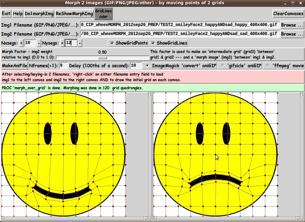
Here is a 'single morph' based on a 50-percent 'intermediate grid'.
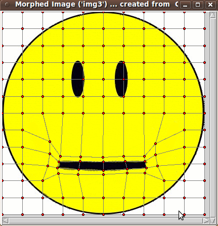
Note that there is a little bit of color-averaging (between black and yellow) showing around the 'lips'. It is hard to avoid this on an image like this without using a much finer grid.
One thing that I found helped avoid too much of this fuzziness was to make the quadrangles just above and below the lips quite narrow --- so that the warping process does not 'drag' the black colors far into the yellow areas.
A resulting animated GIF did not turn out too badly --- but you can see the 'bleeding' of the black into the yellow, in the middle frames of the animation.

I thought a challenging example would be to morph between a rectilinear object and a circular object. Here is an example in which I kept the color issues to a minimum by choosing two objects of similar color.
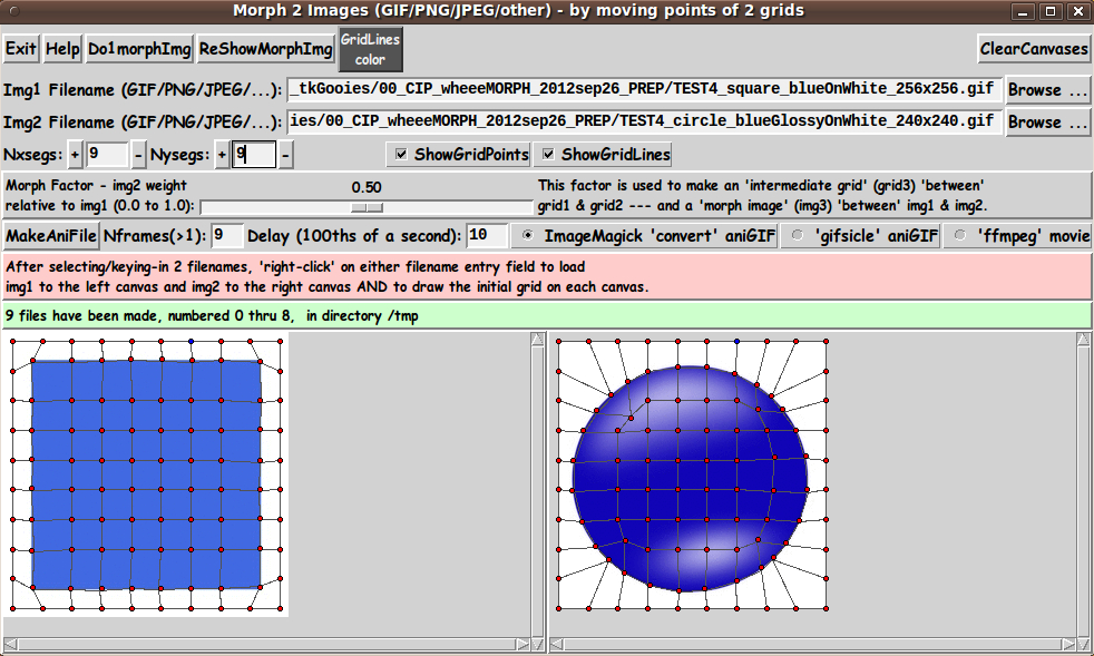
By using the grid above, I was able to generate a pretty good looking animation:

---
On the other hand, here are a couple of square and circular objects in which it is very difficult to map the colors of one nicely onto the colors of the other.
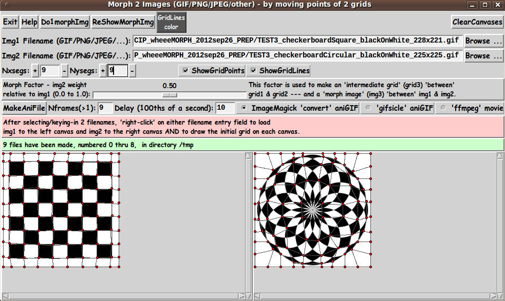
I made a stab at it with the 2 grids shown above, and here is a resulting animation:
There is a lot of 'bleeding' of black into white going on here.
I thought I would try morphing between a drawing and a photo, as seen in the following 2 images and 2 deformed grids:
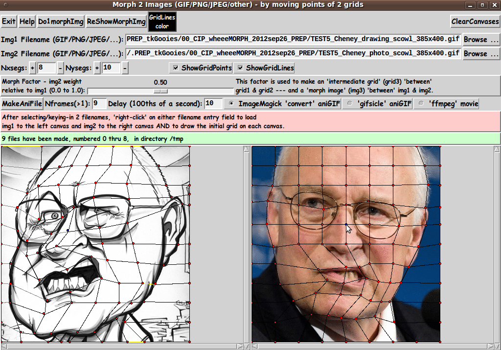
The resulting animation turned up some surprises:

The faces in the 2 images were turned at slightly different angles --- one facing somewhat to the left, the other looking almost straight ahead.
I was rather surprised to see that the morph actually seems to make one head look like it is turning about the neck as one head morphs into the other.
I was also pleasantly surprised at how smoothly the arched upper lip morphed from one image to the other.
I have an old book 'Morphing on Your PC' (1994) by David K. Mason. It was one of my inspirations for writing this script --- especially since it had an old DOS 'DMorph' program on a (rigid) 'floppy disk' that was no longer runnable. (Well it might be, but I was not going to go to great lengths to try to get it running on MS Windows 7 or 8.)
I have long wanted to have a morphing program, so I wanted to make by own 'DMorph' program --- through the magic of Tcl-Tk. That seemed within my grasp after making the 'tkMerge2Images' and 'tkImageGridWarp' scripts mentioned at the top of this page.
In the book, Mason points out some of the things to watch out for in choosing images and making the grids. One thing he pointed out is that it can be rather difficult to map between an human face and an animal face --- although you see it done frequently in movies nowadays.
Mason had a morph of a bear head into an owl head, but it was hard to tell how good the morph was from the rather small, fuzzy, gray-scale images in the book.
And he had a morph of the head of his nephew into the head of the boy's father (Mason's brother-in-law). Mason used those two images to demonstrate gridding techniques. The morph images looked pretty good --- but, again, the pictures were rather small, fuzzy, gray-scale printed images.
I wanted to see how hard it would be to do animal to human (and back), so I chose the following 2 images:
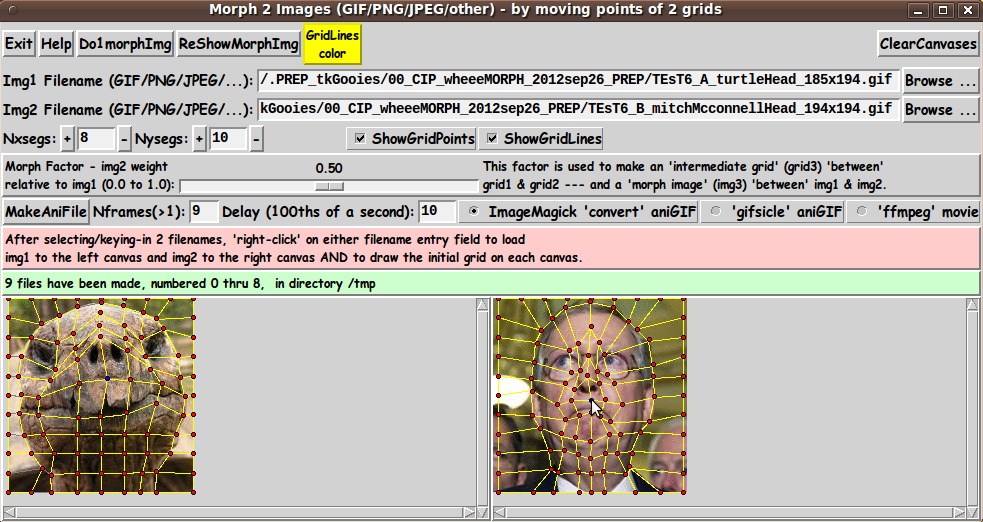
I wasn't very optimistic about the results that I could achieve with the 2 grids above, but I was pretty pleased with how the following animation turned out.
Considering I used only 9 frames, this seemed surprisingly good to me.
In a few preliminary tests with more frames, I have found that using 30 frames (and a delay of about 3 100ths-of-a-second) can sometimes provide a more pleasing animation.
In looking at the examples above, one notices that there is no example of mapping one human face to another --- both in photos. Here are a couple of images of that type:
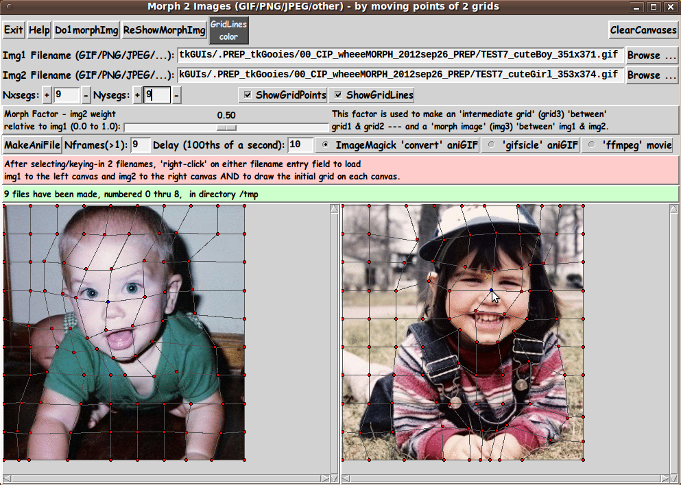
I used a rather crude grid to 'map' one image to the other.
However, it yielded the following animation (with only 9 frames), with which I was pretty pleased.

If I used a finer grid and more frames in the animated-GIF, I could get a smoother 'movie'. But this is a challenging morph, because the head in the left image is tilted to the left and is on the left side of the photo --- whereas the head in the right image is straight up and on theright side of the photo.
Also the hands in the left image are apart whereas the hands in the right image are together. Also there are a lot of color differences in the grid quadrangles (no matter how fine a grid I would use and no matter how 'expert' a mapping I could devise.)
NOTE that this is not a simple graduated 'merging' of 2 images. The head of the left image actually 'warps' into the head of the right image --- that is, there is actual left to right movement of portions of the images.
Also the spread-apart forearms of the image on the left 'morph' (MOVE) into the forearms of the image on the right. Not bad.
INSTALLING THE UTILITY/APP:
The set of files for this utility consists of TWO Tk scripts: the main script 'wheeeMorph.tk' and a color-selector script 'sho_colorvals_via_sliders3rgb.tk' (for setting the color of grid lines).
Those two Tk scripts could be put in a sub-directory of the user's home directory --- such as $HOME/apps/wheeeMorph.
Then the user can use his/her desktop system (such as Gnome or KDE) to set up the main Tk script as an icon on the desktop (or in a desktop 'panel').
Then, whenever the user wants to morph a pair of image files, the user can click on the icon to startup the Tk script.
SOME POSSIBLE ENHANCEMENTS
In using this utility over the next year, I may find that I would like to add a few capabilities, such as
1) Fine control of moving grid-points --- such as the ability to select a grid-point and then move it a pixel at a time with the arrow keys on the keyboard.
2) Ability to 'zoom' into a grid for placing points precisely.
3) Ability to write a deformed grid1 and grid2 to a file, and read the file later, to place the 2 grids on canvas1 and canvas2.
An even more enhanced script would allow for a background-color margin around the images and allow for pushing the 'edge' grid points 'outward' and 'inward'.
---
Handling All the Things a User Could Do With the GUI (90-plus% of the code is there)
I have tried quite a few different operations with the GUI, such as:
* loading a pair of images, then a different (sized) pair of images
* starting with the default grid, then changing Nxsegs and Nysegs
* hiding and showing the grid points and lines --- the 'intermediate' grid (in the popup 'img3' window) as well as grids 1 and 2.
I resolved quite a few issues in the process, but there are probably a few remaining. However, I rejoice that 95% to 99% of the code is in place to achieve the goals I had in mind. Any further fixes and enhancements will probably feel like nothing compared to what I have been through in developing and testing this script.
It rivals the amount of effort that I had to expend in developing the 3D model viewing script at
A 3D Model File Loader-and-Examiner - for OBJ, PLY, OFF, STL, FEA files
There is certainly a lot more challenge in creating a 'robust' interactive Tk script than there is in making a 'demo' Tk script in which a sequence of operations is basically hard-coded in the script --- thus making it unnecessary to handle essentially anything a user might do with a GUI that has quite a few control widgets on it.
IN CONCLUSION
As I have said on several other code-donation pages on this wiki ...
There's a lot to like about a utility that is 'free freedom' --- that is, no-cost and open-source so that you can modify/enhance/fix it without having to wait for someone else to do it for you (which may be never).
A BIG THANK YOU to Ousterhout for starting Tcl-Tk, and a BIG THANK YOU to the Tcl-Tk developers and maintainers who have kept the simply MAH-velous 'wish' interpreter going.